ELECTRICAL KEY OSCILLATOR(for Rear Floor) INSTALLATION
PROCEDURE
-
INSTALL NO. 3 INDOOR ELECTRICAL KEY ANTENNA ASSEMBLY
-
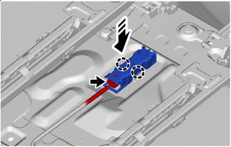

Install in this Direction Engage the claws to install the No. 3 indoor electrical key antenna assembly as shown in the illustration.
Note
Be careful when installing the No. 3 indoor electrical key antenna assembly. If the No. 3 indoor electrical key antenna assembly is dropped, replace it with a new one.
-
Connect the connector.
-
-
CONNECT REAR FLOOR MAT ASSEMBLY RH
-
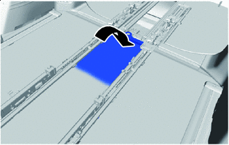

Return Return the rear floor mat assembly RH as shown in the illustration.
-
-
INSTALL LOWER SEAT TRACK RAIL PROTECTOR
-
INSTALL NO. 3 FLOOR CARPET MOULDING
-
INSTALL REAR UPPER NO. 3 FLOOR BOARD PLATE
-
INSTALL UTILITY BOX SUB-ASSEMBLY
-
INSTALL REAR NO. 3 FLOOR BOARD ASSEMBLY
-
INSTALL REAR SEAT LOCK STRIKER COVER LH
-
INSTALL REAR SEAT LOCK STRIKER COVER RH
Tech Tips
Use the same procedure as for the RH side.
-
INSTALL REAR SEAT TRACK SLIDE STOPPER
-
INSTALL REAR NO. 1 SEAT ASSEMBLY LH
-
for Power Captain Seat with Memory:
-
for Power Captain Seat without Memory:
-
for Manual Captain Seat:
-
-
INSTALL REAR NO. 1 SEAT ASSEMBLY RH
-
for Power Captain Seat with Memory:
Tech Tips
Use the same procedure as for the RH side.
-
for Power Captain Seat without Memory:
Tech Tips
Use the same procedure as for the RH side.
-
for Manual Captain Seat:
Tech Tips
Use the same procedure as for the RH side.
-