ELECTRICAL KEY OSCILLATOR(for Rear Floor) REMOVAL
CAUTION / NOTICE / HINT
The necessary procedures (adjustment, calibration, initialization or registration) that must be performed after parts are removed, installed or replaced during the electrical key oscillator removal/installation are shown below.
| Replacement Part or Procedure | Necessary Procedures | Effects/Inoperative when not Performed | Link |
|---|---|---|---|
| Disconnect cable from negative battery terminal | Drive the vehicle until stop and start control is permitted (approximately 15 to 40 minutes) | Stop and start system | |
| Memorize steering angle neutral point | Panoramic view monitor system | ||
| Initialize back door lock | Power door lock control system | ||
| Initialize servo motor | Air conditioning system | ||
| Reset slide door close position | Power slide door system | ||
| Reset back door close position | Power back door system |
PROCEDURE
-
REMOVE FRONT SEAT ASSEMBLY LH (for Super Long Slide Seat)
-
REMOVE REAR NO. 1 SEAT ASSEMBLY LH
-
for Power Captain Seat with Memory:
-
for Power Captain Seat without Memory:
-
for Manual Captain Seat:
-
-
REMOVE REAR NO. 1 SEAT ASSEMBLY RH
-
for Power Captain Seat with Memory:
Tech Tips
Use the same procedure as for the LH side.
-
for Power Captain Seat without Memory:
Tech Tips
Use the same procedure as for the LH side.
-
for Manual Captain Seat:
Tech Tips
Use the same procedure as for the LH side.
-
-
REMOVE REAR SEAT TRACK SLIDE STOPPER
-
REMOVE REAR SEAT LOCK STRIKER COVER LH
-
REMOVE REAR SEAT LOCK STRIKER COVER RH
Tech Tips
Use the same procedure as for the LH side.
-
REMOVE REAR NO. 3 FLOOR BOARD ASSEMBLY
-
REMOVE UTILITY BOX SUB-ASSEMBLY
-
REMOVE REAR NO. 3 FLOOR BOARD UPPER PLATE
-
REMOVE NO. 3 FLOOR CARPET MOULDING
-
REMOVE NO. 4 FLOOR CARPET MOULDING (for Super Long Slide Seat)
-
REMOVE SEAT TRACK LOWER RAIL PROTECTOR
-
REMOVE NO. 6 SEAT TRACK LOWER RAIL PROTECTOR (for Super Long Slide Seat)
-
DISCONNECT REAR FLOOR MAT ASSEMBLY RH
-
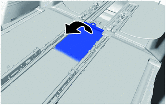

Peel back Peel back the rear floor mat assembly RH to the extent that the No. 3 indoor electrical key antenna assembly can be removed.
Note
Do not use excessive force when peeling back the rear floor mat assembly RH to prevent the foam pad from tearing.
-
-
REMOVE NO. 3 INDOOR ELECTRICAL KEY ANTENNA ASSEMBLY
-
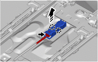

Remove in this Direction Disconnect the connector.
-
Disengage the claws to remove the No. 3 indoor electrical key antenna assembly as shown in the illustration.
Note
Be careful when installing the No. 3 indoor electrical key antenna assembly. If the No. 3 indoor electrical key antenna assembly is dropped, replace it with a new one.
-