THEFT DETERRENT SYSTEM Some Alarm Functions do not Operate
DESCRIPTION
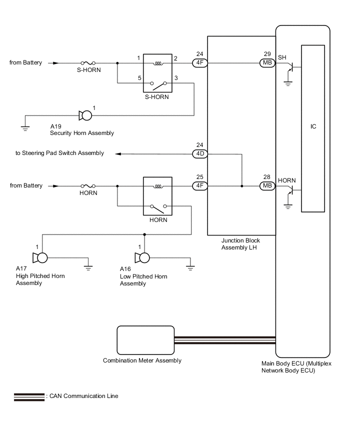
When the alarm sounds, the following alarm functions operate: the hazard lights flash, and the security horn and vehicle horn sound intermittently.
WIRING DIAGRAM
CAUTION / NOTICE / HINT
Note
Inspect the fuses for circuits related to this system before performing the following procedure.
PROCEDURE
-
CHECK THEFT DETERRENT SYSTEM OPERATION
-
Open the driver side window.
-
Set the theft deterrent system.
-
Close all doors and the engine hood.
-
Lock the doors using wireless operation or entry operation.
-
Wait for 9 seconds*1 or 30 seconds*2 or more.
-
*1: w/ Panoramic View Monitor System
-
*2: w/o Panoramic View Monitor System
-
-
-
After 9 seconds*1 or 30 seconds*2 have elapsed, check that the security indicator light changes from illuminated to flashing.
-
*1: w/ Panoramic View Monitor System
-
*2: w/o Panoramic View Monitor System
-
-
Unlock the driver door using the door lock knob.
-
Check that each alarm component operates correctly.
Result Result Proceed to Security horn is not activated A Vehicle horn is not activated B Hazard lights are not activated C
B 
CHECK HORN OPERATION Click here
C 
GO TO LIGHTING SYSTEM Click here
A 
-
-
PERFORM ACTIVE TEST USING GTS (SECURITY HORN)
-
Connect the GTS to the DLC3.
-
Turn the engine switch on (IG).
-
Turn the GTS on.
-
Enter the following menus: Body Electrical / Main Body / Active Test.
-
Perform the Active Test according to the display on the GTS.
Body Electrical > Main Body > Active TestTester Display Measurement Item Control Range Diagnostic Note Security Horn Security horn assembly OFF/ON -
Body Electrical > Main Body > Active TestTester Display Security Horn OK The security horn assembly sounds and stops correctly when operated through the GTS. Result Proceed to OK NG
OK
REPLACE MAIN BODY ECU (MULTIPLEX NETWORK BODY ECU)
NG
-
-
INSPECT S-HORN RELAY
-
Remove the S-HORN relay from the No. 1 engine room relay block RH.
-
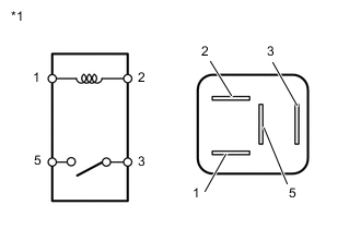
*1 S-HORN Relay Measure the resistance according to the value(s) in the table below.
Standard Resistance Tester Connection Condition Specified Condition 3 - 5 When battery voltage is not applied between terminals 1 and 2 10 kΩ or higher 3 - 5 When battery voltage is applied between terminals 1 and 2 Below 1 Ω Result Proceed to OK NG
NG
REPLACE S-HORN RELAY
OK
-
-
CHECK HARNESS AND CONNECTOR (BATTERY - S-HORN RELAY)
-
Remove the S-HORN relay from the No. 1 engine room relay block RH.
-
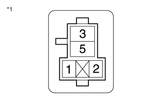
*1 No. 1 Engine Room Relay Block RH Measure the voltage according to the value(s) in the table below.
Standard Voltage Tester Connection Condition Specified Condition 1 (S-HORN relay holder) - Body ground Always 11 to 14 V 5 (S-HORN relay holder) - Body ground Always 11 to 14 V Result Proceed to OK NG
NG
REPAIR OR REPLACE HARNESS OR CONNECTOR
OK
-
-
INSPECT SECURITY HORN ASSEMBLY
-
Remove the security horn assembly.
-
Inspect the security horn assembly.
Result Proceed to OK NG
NG
REPLACE SECURITY HORN ASSEMBLY Click here
OK
-
-
CHECK HARNESS AND CONNECTOR (S-HORN RELAY - SECURITY HORN ASSEMBLY)
-
Remove the S-HORN relay from the No. 1 engine room relay block RH.
-
Disconnect the A19 security horn assembly connector.
-
Measure the resistance according to the value(s) in the table below.
Standard Resistance Tester Connection Condition Specified Condition 3 (S-HORN relay holder) - A19-1 Always Below 1 Ω 3 (S-HORN relay holder) or A19-1 - Body ground Always 10 kΩ or higher Result Proceed to OK NG
NG
REPAIR OR REPLACE HARNESS OR CONNECTOR
OK
-
-
CHECK HARNESS AND CONNECTOR (S-HORN RELAY - JUNCTION BLOCK ASSEMBLY LH)
-
Remove the S-HORN relay from the No. 1 engine room relay block RH.
-
Disconnect the 4F junction block assembly LH connector.
-
Measure the resistance according to the value(s) in the table below.
Standard Resistance Tester Connection Condition Specified Condition 2 (S-HORN relay holder) - 4F-24 Always Below 1 Ω 2 (S-HORN relay holder) or 4F-24 - Body ground Always 10 kΩ or higher Result Proceed to OK NG
NG
REPAIR OR REPLACE HARNESS OR CONNECTOR
OK
-
-
INSPECT JUNCTION BLOCK ASSEMBLY LH
-
Remove the main body ECU (multiplex network body ECU).
-
Disconnect the junction block assembly LH connector.
-
Measure the resistance according to the value(s) in the table below.
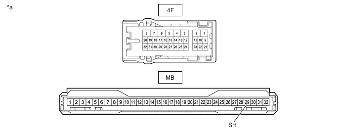
*a Component without harness connected
(Junction Block Assembly LH)
- - Standard Resistance Tester Connection Condition Specified Condition 4F-24 - MB-29 (SH) Always Below 1 Ω Result Proceed to OK NG
OK
REPLACE MAIN BODY ECU (MULTIPLEX NETWORK BODY ECU) Click here
NG
REPLACE JUNCTION BLOCK ASSEMBLY LH Click here
-
-
CHECK HORN OPERATION
-
Press the horn switch and check if the horn sounds.
OK Horn sounds Result Proceed to OK NG
NG
GO TO HORN SYSTEM Click here
OK
-
-
INSPECT JUNCTION BLOCK ASSEMBLY LH
-
Remove the main body ECU (multiplex network body ECU).
-
Disconnect the junction block assembly LH connector.
-
Measure the resistance according to the value(s) in the table below.
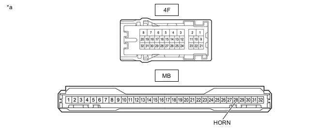
*a Component without harness connected
(Junction Block Assembly LH)
- - Standard Resistance Tester Connection Condition Specified Condition 4F-25 - MB-28 (HORN) Always Below 1 Ω Result Proceed to OK NG
OK
REPLACE MAIN BODY ECU (MULTIPLEX NETWORK BODY ECU) Click here
NG
REPLACE JUNCTION BLOCK ASSEMBLY LH Click here
-