SLIDE DOOR LOCK INSTALLATION
CAUTION / NOTICE / HINT
Tech Tips
-
Use the same procedure for both the LH and RH sides.
-
The procedure described below is for the LH side.
PROCEDURE
-
INSTALL SLIDE DOOR LOCK ASSEMBLY
-
Apply MP grease to the sliding part of the slide door lock assembly.
-
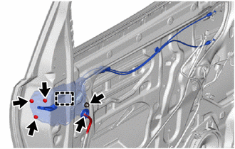
Engage the hook to install the slide door lock assembly.
-
Temporarily install the bolt.
-
Using a T30 "TORX" socket wrench, install the 3 screws.
- Torque:
- 6.8 N*m { 69 kgf*cm, 60 in.*lbf }
-
Tighten the bolt.
- Torque:
- 8.0 N*m { 82 kgf*cm, 71 in.*lbf }
-
Connect the connector.
-
-
INSTALL REAR DOOR WINDOW REAR GUIDE SUB-ASSEMBLY
-
INSTALL REAR DOOR REAR WINDOW FRAME MOULDING
-
INSTALL REAR DOOR GLASS RUN
-
INSTALL REAR DOOR GLASS SUB-ASSEMBLY
-
INSTALL REAR DOOR FRONT BELT SEAL
-
INSTALL REAR DOOR INNER GLASS WEATHERSTRIP WITH GARNISH
-
INSTALL REAR DOOR FRONT WINDOW GUIDE
-
INSTALL SLIDE DOOR WINDOW GARNISH
-
INSTALL NO. 2 SLIDE DOOR SERVICE HOLE COVER
-
INSTALL SLIDE DOOR FRONT LOCK ASSEMBLY
-
Apply MP grease to the sliding part of the slide door front lock assembly.
-
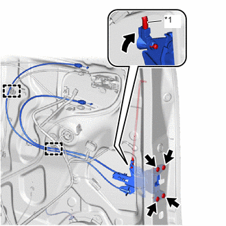
*1 Side Door Lock Open Rod 
Engage Using a T30 "TORX" socket wrench, install the slide door front lock assembly with the 4 screws.
- Torque:
- 7.5 N*m { 76 kgf*cm, 66 in.*lbf }
-
Engage the snap to connect the slide door lock open rod as shown in the illustration.
-
Connect the 2 cables to the clamps.
-
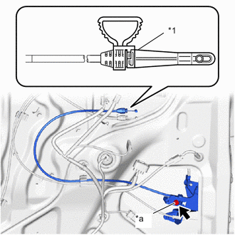
*1 Clamp *a Adjustment Bolt When installing a new slide door front lock assembly:
-
Tighten the adjustment bolt.
- Torque:
- 5.7 N*m { 58 kgf*cm, 50 in.*lbf }
-
Remove the clamp.
-
-
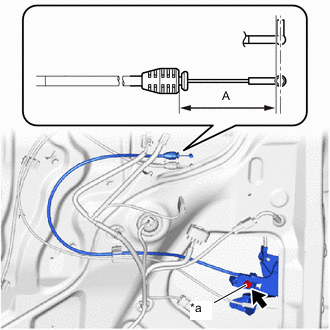
*a Adjustment Bolt When reusing the slide door front lock assembly:
-
Loosen the adjustment bolt.
-
Adjust the cable length as shown in the illustration.
OK Area Measurement A 47.3 mm (1.862 in.) -
Tighten the adjustment bolt.
- Torque:
- 5.7 N*m { 58 kgf*cm, 50 in.*lbf }
-
-
-
INSTALL SLIDE DOOR PANEL COVER SUB-ASSEMBLY
-
INSTALL REAR DOOR LOCKING CONTROL LINK SUB-ASSEMBLY
-
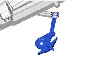
Engage the guide to install the rear door locking control link sub-assembly to the slide door handle assembly.
-
-
INSTALL SLIDE DOOR HANDLE ASSEMBLY
-
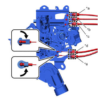
*a Green *b White *c Black *d Yellow *e Gray Engage Engage the guides to connect the 5 cables.
-
Engage the 2 snaps as shown in the illustration.
-
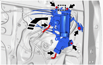

Install in this Direction Engage the hook to install the slide door handle assembly with the 3 bolts as shown in the illustration.
- Torque:
- 7.5 N*m { 76 kgf*cm, 66 in.*lbf }
-
Install the clip.
-
Connect the 2 connectors.
-
-
INSTALL REAR DOOR TRIM BOARD SUB-ASSEMBLY
-
INSTALL NO. 3 SLIDE DOOR WEATHERSTRIP
-
CONNECT CABLE TO NEGATIVE BATTERY TERMINAL
- Torque:
- 5.4 N*m { 55 kgf*cm, 48 in.*lbf }
Note
When disconnecting the cable, some systems need to be initialized after the cable is reconnected.
-
INITIALIZE POWER WINDOW CONTROL SYSTEM
-
INSPECT POWER WINDOW OPERATION