SLIDE DOOR LOCK REMOVAL
CAUTION / NOTICE / HINT
The necessary procedures(adjustment, calibration, initialization, or registration) that must be performed after parts are removed, installed, or replaced during the slide door lock removal/installation are shown below.
| Replacement Part or Procedure | Necessary Procedures | Effects/Inoperative when not Performed | Link |
|---|---|---|---|
| Disconnect cable from negative battery terminal | Drive the vehicle until stop and start control is permitted (approximately 15 to 40 minutes) | Stop and start system | |
| Memorize steering angle neutral point | Panoramic view monitor system | ||
| Initialize back door lock | Power door lock control system | ||
| Initialize servo motor | Air conditioning system | ||
| Reset slide door close position | Power slide door system | ||
| Reset back door close position | Power back door system | ||
|
Initialize Power Window Control System |
|
Tech Tips
-
Use the same procedure for both the LH and RH sides.
-
The procedure described below is for the LH side.
PROCEDURE
-
PRECAUTION
Note
After turning the engine switch off, waiting time may be required before disconnecting the cable from the negative (-) battery terminal. Therefore, make sure to read the disconnecting the cable from the negative (-) battery terminal notices before proceeding with work.
-
DISCONNECT CABLE FROM NEGATIVE BATTERY TERMINAL
Note
When disconnecting the cable, some systems need to be initialized after the cable is reconnected.
-
REMOVE NO. 3 SLIDE DOOR WEATHERSTRIP
-
REMOVE REAR DOOR TRIM BOARD SUB-ASSEMBLY
-
REMOVE SLIDE DOOR HANDLE ASSEMBLY
-
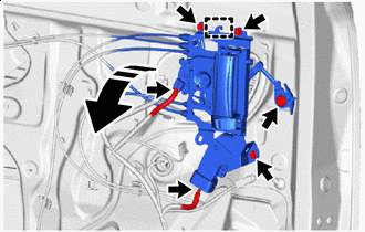

Remove in this Direction Disconnect the 2 connectors.
-
Remove the clip.
-
Remove the 3 bolts and disengage the hook to separate the slide door handle assembly as shown in the illustration.
-
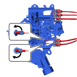

Disengage Disengage the 2 snaps as shown in the illustration.
-
Disengage the guides and disconnect the 5 cables to remove the slide door handle assembly.
-
-
REMOVE REAR DOOR LOCKING CONTROL LINK SUB-ASSEMBLY
-
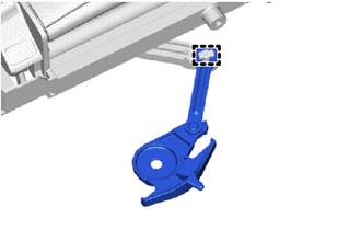
Disengage the guide to remove the rear door locking control link sub-assembly from the slide door handle assembly.
-
-
REMOVE SLIDE DOOR PANEL COVER SUB-ASSEMBLY
-
REMOVE SLIDE DOOR FRONT LOCK ASSEMBLY
-
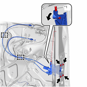
*1 Slide Door Lock Open Rod Disengage Disconnect the 2 cables from the clamps.
-
Disengage the snap to disconnect the slide door lock open rod as shown in the illustration.
-
Using a T30 "TORX" socket wrench, remove the 4 screws and slide door front lock assembly.
-
-
REMOVE NO. 2 SLIDE DOOR SERVICE HOLE COVER
-
REMOVE SLIDE DOOR WINDOW GARNISH
-
REMOVE REAR DOOR WINDOW FRONT GUIDE
-
REMOVE REAR DOOR GLASS INNER WEATHERSTRIP WITH GARNISH
-
REMOVE REAR DOOR GLASS SUB-ASSEMBLY
-
REMOVE REAR DOOR GLASS RUN
-
REMOVE REAR DOOR WINDOW REAR FRAME MOULDING
-
REMOVE REAR DOOR WINDOW REAR GUIDE SUB-ASSEMBLY
-
REMOVE SLIDE DOOR LOCK ASSEMBLY
-
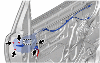
Disconnect the connector.
-
Using a T30 "TORX" socket wrench, remove the 3 screws.
-
Remove the bolt.
-
Disengage the hook to remove the slide door lock assembly.
-