BACK DOOR LOCK INSPECTION
PROCEDURE
-
INSPECT BACK DOOR LOCK ASSEMBLY
-
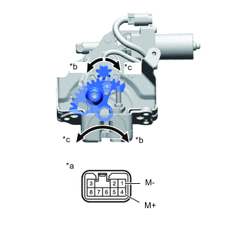
*a Component without harness connected
(Back Door Lock Assembly)
*b Direction of Close Operation *c Direction of Open Operation Check the operation.
-
Apply battery voltage and check the operation of the closer motor.
OK Battery Connection Result Battery positive (+) - 1 (M-)
Battery negative (-) - 4 (M+)
Close Operation Battery positive (+) - 4 (M+)
Battery negative (-) - 1 (M-)
Open Operation If the result is not as specified, replace the back door lock assembly.
-
-
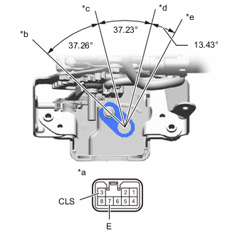
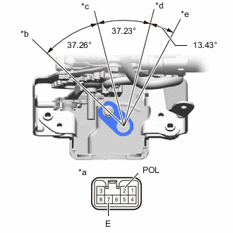
*a Component without harness connected
(Back Door Lock Assembly)
*b Open Position *c Half-latch Position *d Full-latch Position *e Over Stroke Position Check the resistance of the half latch switch.
-
Measure the resistance according to the value(s) in the table below. (Direction Close Operation)
Standard Resistance Tester Connection Condition Specified Condition 3 (CLS) - 7 (E) Open position Below 1 Ω 3 (CLS) - 7 (E) Open position → Half-latch position Below 1 Ω → 10 kΩ or higher 3 (CLS) - 7 (E) Half-latch position 10 kΩ or higher 3 (CLS) - 7 (E) Full-latch position 10 kΩ or higher 3 (CLS) - 7 (E) Over stroke position 10 kΩ or higher If the result is not as specified, replace the back door lock assembly.
-
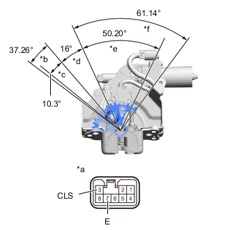
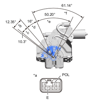
*a Component without harness connected
(Back Door Lock Assembly)
*b Full Stroke Area *c Open Area *d Neutral Area *e Full-latch Area *f Over Stroke Area Measure the resistance according to the value(s) in the table below. (Direction Open Operation)
Standard Resistance Tester Connection Condition Specified Condition 3 (CLS) - 7 (E) Full-latch position 10 kΩ or higher 3 (CLS) - 7 (E) Open position 10 kΩ or higher 3 (CLS) - 7 (E) Open position → Full stroke position 10 kΩ or higher → Below 1 Ω 3 (CLS) - 7 (E) Full stroke position Below 1 Ω If the result is not as specified, replace the back door lock assembly.
-
-

*a Component without harness connected
(Back Door Lock Assembly)
*b Open Position *c Half-latch Position *d Full-latch Position *e Over Stroke Position Check the resistance of the full latch switch.
-
Measure the resistance according to the value(s) in the table below. (Direction Close Operation)
Standard Resistance Tester Connection Condition Specified Condition 7 (E) - 8 (CTY) Open position Below 1 Ω 7 (E) - 8 (CTY) Half-latch position Below 1 Ω 7 (E) - 8 (CTY) Half-latch position → Full-latch position Below 1 Ω → 10 kΩ or higher 7 (E) - 8 (CTY) Full-latch position 10 kΩ or higher 7 (E) - 8 (CTY) Over stroke position 10 kΩ or higher If the result is not as specified, replace the back door lock assembly.
-
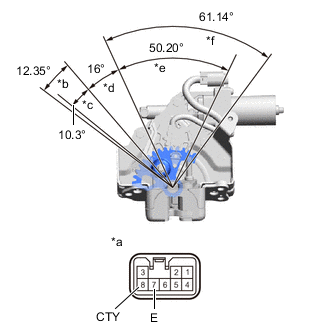
*a Component without harness connected
(Back Door Lock Assembly)
*b Full Stroke Area *c Open Area *d Neutral Area *e Full-latch Area *f Over Stroke Area Measure the resistance according to the value(s) in the table below. (Direction Open Operation)
Standard Resistance Tester Connection Condition Specified Condition 7 (E) - 8 (CTY) Full-latch position 10 kΩ or higher 7 (E) - 8 (CTY) Full-latch position → Open position 10 kΩ or higher → Below 1 Ω 7 (E) - 8 (CTY) Open position Below 1 Ω 7 (E) - 8 (CTY) Full stroke position Below 1 Ω If the result is not as specified, replace the back door lock assembly.
-
-
*a Component without harness connected
(Back Door Lock Assembly)
*b Open Position *c Half-latch Position *d Full-latch Position *e Over Stroke Position Check the resistance of the ratchet switch.
-
Measure the resistance according to the value(s) in the table below. (Direction Close Operation)
Standard Resistance Tester Connection Condition Specified Condition 2 (POL) - 7 (E) Open position 10 kΩ or higher 2 (POL) - 7 (E) Open position → Half-latch position 10 kΩ or higher → Below 1 Ω → 10 kΩ or higher 2 (POL) - 7 (E) Half-latch position 10 kΩ or higher 2 (POL) - 7 (E) Half-latch position → Full-latch position 10 kΩ or higher → Below 1 Ω → 10 kΩ or higher 2 (POL) - 7 (E) Full-latch position 10 kΩ or higher 2 (POL) - 7 (E) Over stroke position 10 kΩ or higher If the result is not as specified, replace the back door lock assembly.
-
*a Component without harness connected
(Back Door Lock Assembly)
*b Full Stroke Area *c Open Area *d Neutral Area *e Full-latch Area *f Over Stroke Area Measure the resistance according to the value(s) in the table below. (Direction Open Operation)
Standard Resistance Tester Connection Condition Specified Condition 2 (POL) - 7 (E) Full-latch position 10 kΩ or higher 2 (POL) - 7 (E) Full-latch position → Open position 10 kΩ or higher → Below 1 Ω 2 (POL) - 7 (E) Open position Below 1 Ω 2 (POL) - 7 (E) Full stroke position Below 1 Ω 2 (POL) - 7 (E) Full stroke position → Open position Below 1 Ω→ 10 kΩ or higher If the result is not as specified, replace the back door lock assembly.
-
-
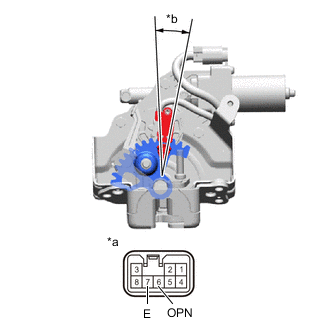
*a Component without harness connected
(Back Door Lock Assembly)
*b Sector Gear in Neutral Position Check the resistance of the sector switch.
-
Measure the resistance according to the value(s) in the table below.
Standard Resistance Tester Connection Condition Specified Condition 6 (OPN) - 7 (E) Sector gear in neutral position
(Sector switch on)
Below 1 Ω 6 (OPN) - 7 (E) Sector gear not in neutral position
(Sector switch off)
10 kΩ or higher If the result is not as specified, replace the back door lock assembly.
-
-