POWER DOOR LOCK CONTROL SYSTEM Collision Door Lock Release Function does not Operate
DESCRIPTION
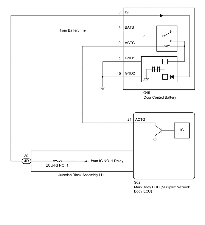
When an impact is detected, a relay inside the door control battery is operated to switch the power source of the door lock with motor assemblies from the vehicle battery to the door control battery.
WIRING DIAGRAM
CAUTION / NOTICE / HINT
Note
-
When using the GTS with the vehicle engine switch off, connect the GTS to the DLC3 and turn a courtesy light switch on and off at intervals of 1.5 seconds or less until communication between the GTS and the vehicle begins. Then select Model Code "KEY REGIST" under manual mode and enter the following menus: Body Electrical / Entry&Start(CAN). While using the GTS, periodically turn a courtesy light switch on and off at intervals of 1.5 seconds or less to maintain communication between the GTS and the vehicle.
-
Inspect the fuses for circuits related to this system before performing the following procedure.
-
If the main body ECU (multiplex network body ECU) is replaced, refer to Service Bulletin.
-
As the door control battery is installed between the vehicle battery and main body ECU (multiplex network body ECU), first perform the inspections in How to Proceed with Troubleshooting to confirm that there are no malfunctions in the power source circuit for the main body ECU (multiplex network body ECU) before performing this troubleshooting procedure.
PROCEDURE
-
CHECK DOOR LOCK OPERATION
-
Check door lock operation.
OK All doors lock and unlock normally. Result Proceed to OK NG
NG 
GO TO PROBLEM SYMPTOMS TABLE Click here
OK 
-
-
CHECK DOOR CONTROL BATTERY (BATTERY VOLTAGE)
-
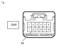
*a Front view of wire harness connector
(to Door Control Battery)
Disconnect the door control battery connector.
-
Measure the voltage according to the value(s) in the table below.
Standard Voltage Tester Connection Switch Condition Specified Condition G49-8 (IG) - Body ground Engine switch on (IG) 11 to 14 V Result Proceed to OK NG
NG 
CHECK HARNESS AND CONNECTOR (JUNCTION BLOCK ASSEMBLY LH - DOOR CONTROL BATTERY) Click here
OK
-
-
CHECK HARNESS AND CONNECTOR (MAIN BODY ECU (MULTIPLEX NETWORK BODY ECU) - DOOR CONTROL BATTERY)
-
Disconnect the G62 main body ECU (multiplex network body ECU) connector.
-
Disconnect the G49 door control battery connector.
-
Measure the resistance according to the value(s) in the table below.
Standard Resistance Tester Connection Condition Specified Condition G62-21 (ACTG) - G49-9 (ACTG) Always Below 1 Ω G62-21 (ACTG) or G49-9 (ACTG) - Body ground Always 10 kΩ or higher Result Proceed to OK NG
NG
REPAIR OR REPLACE HARNESS OR CONNECTOR
OK
-
-
REPLACE DOOR CONTROL BATTERY
-
Replace the door control battery with a new or known good one.
Result Proceed to NEXT
NEXT
-
-
CHECK DOOR CONTROL BATTERY
-
Check door control battery operation.
OK Collision detection door lock function operates normally. Result Proceed to OK NG
OK
END (DOOR CONTROL BATTERY WAS DEFECTIVE)
NG
REPLACE MAIN BODY ECU (MULTIPLEX NETWORK BODY ECU) Click here
-
-
CHECK HARNESS AND CONNECTOR (JUNCTION BLOCK ASSEMBLY LH - DOOR CONTROL BATTERY)
-
Disconnect the 4D junction block assembly LH connector.
-
Disconnect the G49 door control battery connector.
-
Measure the resistance according to the value(s) in the table below.
Standard Resistance Tester Connection Condition Specified Condition 4D-20 - G49-8 (IG) Always Below 1 Ω 4D-20 or G49-8 (IG) - Body ground Always 10 kΩ or higher Result Proceed to OK NG
NG
REPAIR OR REPLACE HARNESS OR CONNECTOR
OK
-
-
CHECK JUNCTION BLOCK ASSEMBLY LH (BATTERY VOLTAGE)
-
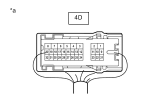
*a Component with harness connected
(Junction Block Assembly LH)
Disconnect the junction block assembly LH.
-
Measure the voltage according to the value(s) in the table below.
Standard Voltage Tester Connection Switch Condition Specified Condition 4D-20 - Body ground Engine switch on (IG) 11 to 14 V Result Proceed to OK NG
OK
REPLACE JUNCTION BLOCK ASSEMBLY LH Click here
NG
GO TO LIGHTING SYSTEM (IG Signal Circuit) Click here
-