NETWORK GATEWAY ECU REMOVAL
CAUTION / NOTICE / HINT
The necessary procedures (adjustment, calibration, initialization, or registration) that must be performed after parts are removed, installed, or replaced during the network gateway ECU removal/installation are shown below.
| Replacement Part or Procedure | Necessary Procedures | Effects/Inoperative when not Performed | Link |
|---|---|---|---|
| Battery terminal is disconnected/reconnected | Drive the vehicle until stop and start control is permitted (approximately 5 to 60 minutes) | Stop and Start System (for 2AR-FE) | |
| Stop and Start System (for 2GR-FKS) | |||
| Memorize steering angle neutral point | Panoramic view monitor system | ||
| Initialize back door lock | Power door lock control system | ||
| Initialize servo motor | Air Conditioning System | ||
| Reset slide door close position | Power slide door system | ||
| Reset back door close position | Power back door system |
CAUTION:
Some of these service operations affect the SRS airbag system. Read the precautionary notices concerning the SRS airbag system before servicing.
Note
-
When disassembling the network gateway ECU, eliminate static electricity by touching the vehicle body to prevent the components from being damaged.
-
After turning the engine switch off, waiting time may be required before disconnecting the cable from the negative (-) battery terminal. Therefore, make sure to read the disconnecting the cable from the negative (-) battery terminal notices before proceeding with work.
PROCEDURE
-
DISCONNECT CABLE FROM NEGATIVE BATTERY TERMINAL
Note
When disconnecting the cable, some systems need to be initialized after the cable is reconnected.
-
REMOVE COMBINATION METER ASSEMBLY
-
REMOVE CENTRAL GATEWAY ECU (NETWORK GATEWAY ECU)
-
for LHD
-
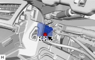
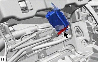
Remove the bolt.
-
Disengage the guide and central gateway ECU (network gateway ECU) from the instrument panel reinforcement assembly.
-
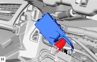
Disconnect the central gateway ECU (network gateway ECU) connector.
-
-
for RHD
-
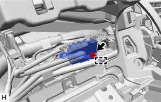
Remove the bolt.
-
Disengage the guide and central gateway ECU (network gateway ECU) from the instrument panel reinforcement assembly.
-
Disconnect the central gateway ECU (network gateway ECU) connector.
-
-