AIR CONDITIONING SYSTEM SYSTEM DESCRIPTION
-
GENERAL
-
The air conditioning system has the following controls.
Control Outline Neural Network Control This control is capable of performing complex control by artificially simulating the information processing method of the nervous system of living organisms in order to establish a complex input/output relationship similar to that of a human brain. Outlet Air Temperature Control Based on the temperature set by the temperature control dial, neural network control calculates outlet air temperature based on input signals from various sensors. Left and Right Independent Control The temperature settings for the driver and front passenger are controlled independently in order to provide separate vehicle interior temperatures for the right and left sides of the vehicle. Blower Control Controls the blower motor in accordance with the airflow volume that has been calculated by neural network control based on the input signals from various sensors. Air Outlet Control Automatically switches the air outlets in accordance with the outlet mode that has been calculated by neural network control. In accordance with the engine coolant temperature, ambient air temperature, amount of sunlight, required blower, outlet temperature and vehicle speed conditions, this control automatically switches the blower outlet to foot and defroster mode to prevent the windows from becoming fogged up when the ambient air temperature is low. Air Inlet Control Automatically controls the air inlet control damper to help achieve the calculated outlet air temperature that is required. Drives the air inlet control servo motor according to the operation of the air inlet control switch and moves the dampers to the fresh or recirculation position. Automatic Recirculation Control*1 Automatically changes the air inlet mode to fresh air or recirculate mode according to the level of harmful elements in the outside air, cabin temperature, ambient temperature and vehicle speed. Compressor Control Through the calculation of the target evaporator temperature based on various sensor signals, the air conditioning amplifier optimally controls discharge capacity by regulating the opening extent of the compressor solenoid valve. PTC Heater Control*2 When the engine switch is turned on (IG), and the blower motor is turned on, the air conditioning amplifier assembly turns on the PTC heater (quick heater assembly) if the following conditions are met.
-
Engine coolant temperature is below specified temperature.
-
Ambient temperature is below specified temperature.
-
Tentative air mix damper opening angle is above the specified value (MAX HOT).
ECO Drive Mode Control When set to ECO drive mode, the air conditioning amplifier assembly decreases the blower speed. Electric Power Control
-
When the vehicle voltage is below the specified level, the air conditioning amplifier assembly save the power source of some systems in accordance with the voltage signal.
-
When the electric power control is operating, the combination meter assembly warns the driver by indicating a message on the multi-information display.
Ion Generator Control*3 When ion generator operation mode is on, the ion generator sub-assembly operates together with the rotation of the blower motor. Defroster Control Defroster control logic is used to improve defroster performance. Diagnosis A Diagnostic Trouble Code (DTC) is stored in memory when the air conditioning amplifier detects a problem with the air conditioning system.
-
*1: w/ Automatic Recirculation/fresh Control Function
-
*2: w/ PTC Heater
-
*3: w/ Ion Generator
-
-
-
MODE POSITION AND DAMPER OPERATION
-
Mode Position and Damper Operation
Figure 1. for LHD:
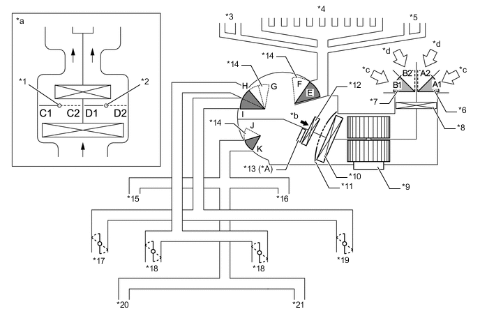
*A w/ PTC Heater - - *1 Driver Side Air Mix Control Damper *2 Front Passenger Side Air Mix Control Damper *3 Driver Side Side Defroster *4 Front Defroster *5 Front Passenger Side Side Defroster *6 Air Inlet Control Damper (Lower Side) *7 Air Inlet Control Damper (Upper Side) *8 Clean Air Filter *9 Blower with Fan Motor Sub-assembly *10 No. 1 Cooler Evaporator Sub-assembly *11 Air Mix Control Damper *12 Heater Radiator Unit Sub-assembly *13 PTC Heater (Quick Heater Assembly) *14 Mode Switching Damper *15 Driver Side Footwell Register *16 Front Passenger Side Footwell Register *17 Driver Side Side Register *18 Center Register *19 Front Passenger Side Side Register *20 Driver Side Rear Footwell Register *21 Front Passenger Side Rear Footwell Register - - *a Illustration Image View from [A] *b [A] View *c Recirculated Air *d Fresh Air Figure 2. for RHD:
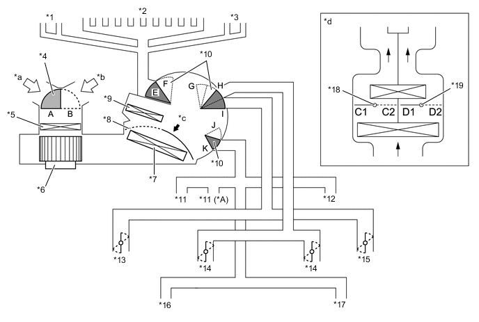
*A for Super Long Slide Seat - - *1 Front Passenger Side Side Defroster *2 Front Defroster *3 Driver Side Side Defroster *4 Air Inlet Control Door *5 Clean Air Filter *6 Blower with Fan Motor Sub-assembly *7 No. 1 Cooler Evaporator Sub-assembly *8 Air Mix Control Door *9 Heater Radiator Unit Sub-assembly *10 Mode Switching Door *11 Front Passenger Side Footwell Register *12 Driver Side Footwell Register *13 Front Passenger Side Side Register *14 Center Register *15 Driver Side Side Register *16 Front Passenger Side Rear Footwell Register *17 Driver Side Rear Footwell Register *18 Front Passenger Side Air Mix Control Door *19 Driver Side Air Mix Control Door - - *a Fresh Air *b Recirculated Air *c [A] View *d Illustration Image View from [A] Figure 3. for Rear:
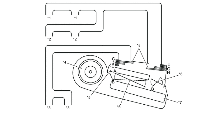
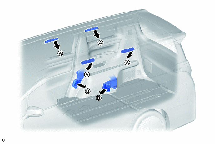
*1 Roof Side Register RH *2 Roof Side Register LH *3 Rear Footwell Register *4 Rear Blower Motor with Fan Sub-assembly *5 Heater Radiator Unit Sub-assembly *6 Air Mix Control Damper *7 Rear Evaporator Sub-assembly *8 Mode Switching Damper
-
for Front:
Functions of Main Dampers Control Damper Operation Position Damper Position Operation Air Inlet Control Damper (w/ Automatic Recirculation/fresh Control Function) FRESH A1, B1 Allows fresh air to enter. RECIRCULATION A2, B2 Causes internal air to recirculate. Air Mix Control Damper Temperature Setting: 16°C (61°F) to 30°C (86°F) C1 - C2 Varies the front passenger side mixture ratio of the fresh air and the recirculation air in order to regulate the temperature continuously from HI to LO. D2 - D1 Varies the driver side mixture ratio of the fresh air and the recirculation air in order to regulate the temperature continuously from HI to LO. Air Outlet Control Damper DEF

F, H, K Defrosts the windshield through the center defroster, side defrosters and side registers. FOOT / DEF

F, H, J to K Defrosts the windshield through the center defroster, side defrosters, side registers, and rear center register, while air is also blown out from the front and rear footwell register ducts. FOOT

E, (E to F)*, H, J Air blows out of the front and rear footwell register ducts, and side registers. In addition, air blows out slightly from the center defroster and side defrosters. BI-LEVEL

E, G to I, J to K Air blows out of the front and rear center registers, side registers and front and rear footwell register ducts. FACE

E, G, K Air blows out of the front and rear center registers, and side registers.
-
*: The automatic air conditioning system is operating.
-
-
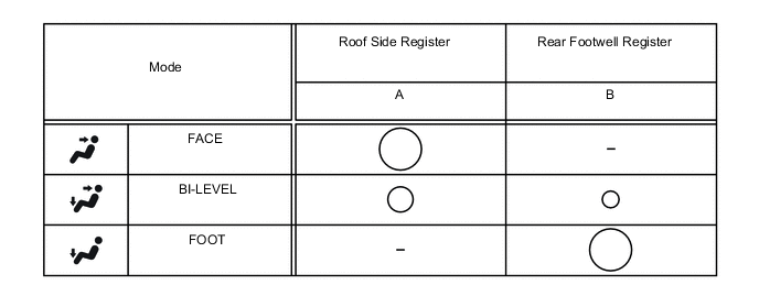
for Rear:
Functions of Main Dampers Control Damper Operation Position Damper Position Operation Air Mix Control Damper Temperature Setting: 16°C (61°F) to 30°C (86°F) A to B Varies the mixture ratio of warm air and cool air in order to continuously regulate the temperature between MAX HOT and MAX COOL. Air Outlet Control Damper FOOT
E, H Air blows out of the rear footwell registers. BI-LEVEL
D, G Air blows out of the roof side registers and rear footwell registers. FACE
C, F Air blows out of the roof side registers.
-
-
-
AIR OUTLETS AND AIRFLOW VOLUME
-
Air Outlets and Airflow Volume
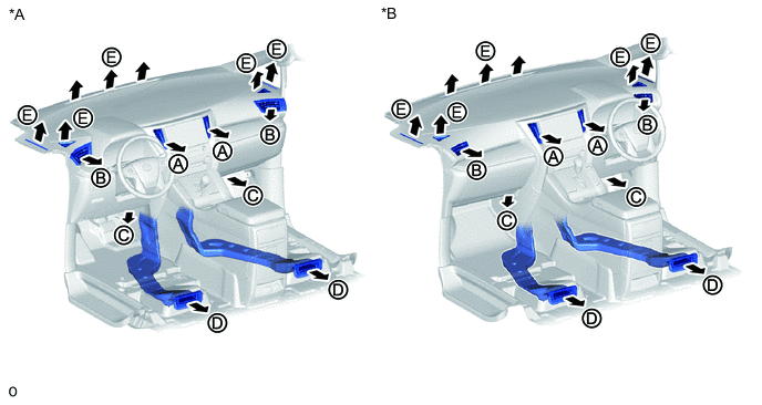
*A for LHD *B for RHD 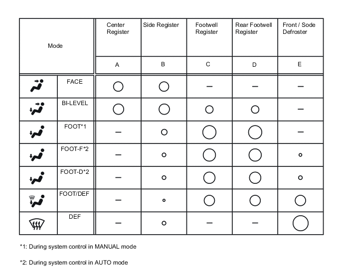
Tech Tips
The circle size (○) indicates the proportion of air flow volume.
-