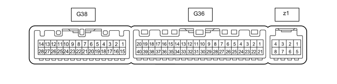
AIR CONDITIONING SYSTEM TERMINALS OF ECU
-
AIR CONDITIONING AMPLIFIER ASSEMBLY
-
Disconnect the G36 and G38 air conditioning amplifier assembly connectors.
-
Measure the resistance and voltage according to the value(s) in the table below.
Terminal No.
(Symbol)
Wiring Color Terminal Description Condition Specified Condition G36-1 (IG+) - Body ground V - Body ground Power source (IG) Engine switch on (IG) 11 to 14 V Engine switch off Below 1 V G36-14 (GND) - Body ground W-B - Body ground Ground Always Below 1 Ω G36-21 (B) - Body ground P - Body ground Power source (Back-up) Always 11 to 14 V G38-24 (GND2) - Body ground BR - Body ground Ground Always Below 1 Ω G38-28 (+B2) - Body ground SB - Body ground Power source (Back-up) Always 11 to 14 V -
Reconnect the G36 and G38 air conditioning amplifier assembly connectors.
-
Measure the resistance and voltage, and check for waveform according to the value(s) in the table below.
Terminal No.
(Symbol)
Wiring Color Terminal Description Condition Specified Condition G36-2 (SOL+) - Body ground R - Body ground Compressor solenoid operation signal
-
Engine running
-
"A/C" switch on
-
Blower switch: LO
Pulse generation
(See waveform 1)
G36-3 (PTC2) - Body ground*1 LG - Body ground Quick heater assembly operation signal
-
Engine starts
-
Combination switch assembly (ECO mode switch) off
-
Temperature settings: MAX HOT
-
Ambient temperature: 10°C (50°F) or lower
-
Engine coolant temperature: 64°C (147°F) or lower
-
Light control switch off
-
Blower switch: off → on (after 20 seconds)
11 to 14 V → Below 1 V G36-4 (ECON) - Body ground SB - Body ground Combination switch assembly (ECO mode switch) signal
-
Engine switch on (IG)
-
Combination switch assembly (ECO mode switch) on
Below 1 V
-
Engine switch on (IG)
-
Combination switch assembly (ECO mode switch) off
11 to 14 V G36-5 (TAM) - G36-13 (SG-2) P - B Ambient temperature sensor signal
-
Engine switch on (IG) (do not start the engine and electric motor)
-
Ambient temperature: 10°C (50°F)
1.8 to 2.4 V
-
Engine switch on (IG) (do not start the engine and electric motor)
-
Ambient temperature: 15°C (59°F)
1.65 to 2.15 V
-
Engine switch on (IG) (do not start the engine and electric motor)
-
Ambient temperature: 20°C (68°F)
1.5 to 1.95 V
-
Engine switch on (IG) (do not start the engine and electric motor)
-
Ambient temperature: 25°C (77°F)
1.35 to 1.75 V
-
Engine switch on (IG) (do not start the engine and electric motor)
-
Ambient temperature: 30°C (86°F)
1.2 to 1.55 V
-
Engine switch on (IG) (do not start the engine and electric motor)
-
Ambient temperature: 35°C (95°F)
1.0 to 1.4 V
-
Engine switch on (IG) (do not start the engine and electric motor)
-
Ambient temperature: 40°C (104°F)
0.85 to 1.25 V
-
Engine switch on (IG) (do not start the engine and electric motor)
-
Ambient temperature: 45°C (113°F)
0.75 to 1.10 V
-
Engine switch on (IG) (do not start the engine and electric motor)
-
Ambient temperature: 50°C (122°F)
0.65 to 1.0 V G36-8 (LOCK) - Body ground*2 G - Body ground Compressor with pulley assembly signal
-
Engine running
-
"A/C" switch on
-
Blower switch: LO
Pulse generation
(See waveform 4)
G36-9 (PRE) - G36-13 (SG-2) SB - B Air conditioner pressure sensor signal
-
Engine running
-
Air conditioning system operating
-
Refrigerant pressure: Abnormal pressure (higher than 3025 kPa [30.8 kgf/cm2, 439 psi])
4.73 V or higher
-
Engine running
-
Air conditioning system operating
-
Refrigerant pressure: Abnormal pressure (below 176 kPa [1.8 kgf/cm2, 26 psi])
Below 0.62 V Engine running
-
Engine running
-
Air conditioning system operating
-
Refrigerant pressure: Normal pressure (below 3025 kPa [30.8 kgf/cm2, 439 psi] and higher than 176 kPa [1.8 kgf/cm2, 26 psi])
0.62 to 4.73 V G36-10 (S5-3) - Body ground GR - Body ground Power source of air conditioner pressure sensor, ambient temperature sensor, air conditioning lock sensor*2 Engine switch on (IG) 4.75 to 5.25 V G36-11 (CANH) BE CAN communication line - - G36-12 (CANL) W CAN communication line - - G36-13 (SG-2) - Body ground B - Body ground Ground for ambient temperature sensor signal Always Below 1 Ω G36-15 (NANO) - Body ground*3 G - Body ground No. 1 ion generator sub-assembly operation signal
-
Engine switch on (IG)
-
Blower switch: LO
Below 1 V
-
Engine switch on (IG)
-
Blower switch: off
11 to 14 V G36-16 (RNNO) - Body ground*3 GR - Body ground No. 2 ion generator sub-assembly operation signal
-
Engine switch on (IG)
-
Blower switch: LO
Below 1 V
-
Engine switch on (IG)
-
Blower switch: off
11 to 14 V G36-20 (MGC) - Body ground*2 G - Body ground Magnet clutch relay signal
-
Engine running
-
"A/C" switch off → on
-
Blower switch: LO
-
Magnet clutch assembly off → on
11 to 14 V → Below 1 V G36-22 (BLW) - Body ground Y - Body ground Blower motor speed control signal
-
Engine switch on (IG)
-
Blower switch: LO
Pulse generation
(See waveform 2)
G36-25 (RNIN) - Body ground*3 R - Body ground No. 2 ion generator sub-assembly condition signal
-
Engine switch on (IG)
-
Blower switch: LO
Below 1 V
-
Engine switch on (IG)
-
Blower switch: off
4.75 to 5.25 V G36-26 (NAIN) - Body ground*3 LG - Body ground No. 1 ion generator sub-assembly condition signal
-
Engine switch on (IG)
-
Blower switch: LO
Below 1 V
-
Engine switch on (IG)
-
Blower switch: off
4.75 to 5.25 V G36-29 (TR) - G36-34 (SG-4) B - LG Room temperature sensor signal
-
Engine switch on (IG)
-
Cabin temperature: 25°C (77°F)
1.8 to 2.2 V
-
Engine switch on (IG)
-
Cabin temperature: 40°C (104°F)
1.2 to 1.6 V G36-34 (SG-4) - Body ground LG - Body ground Ground for room temperature sensor Always Below 1 Ω G36-35 (SG-5) - Body ground V - Body ground Ground for smog ventilation sensor Always Below 1 Ω G36-36 (PTC3) - Body ground*1 Y - Body ground Quick heater assembly operation signal
-
Engine starts
-
Combination switch assembly (ECO mode switch) off
-
Temperature settings: MAX HOT
-
Ambient temperature: 10°C (50°F) or lower
-
Engine coolant temperature: 64°C (147°F) or lower
-
Light control switch off
-
Blower switch: off → on (after 30 seconds)
11 to 14 V → Below 1 V G36-37 (LIN1) - Body ground BE - Body ground LIN communication signal Engine switch on (IG) Pulse generation G36-40 (PTC1) - Body ground*1 R - Body ground Quick heater assembly operation signal
-
Engine starts
-
Combination switch assembly (ECO mode switch) off
-
Temperature settings: MAX HOT
-
Ambient temperature: 10°C (50°F) or lower
-
Engine coolant temperature: 60°C (140°F) or lower
-
Light control switch off
-
Blower switch: off → on (after 10 seconds)
11 to 14 V → Below 1 V G38-1 (RBUS) - G38-25 (RBUG) B - GR BUS IC control signal Engine switch on (IG) Pulse generation
(See waveform 5)
G38-3 (DGS) - G36-35 (SG-5)*4 W - V Smog ventilation sensor signal (HC, CO) After 28 seconds from engine switch on (IG) and sensor exposed to exhaust gas (HC, CO) 1.0 to 4.5 V G38-4 (DGS1) - G36-35 (SG-5)*4 BE - V Smog ventilation sensor signal (NOx) After 120 seconds from engine switch on (IG) and sensor exposed to exhaust gas (NOx) 1.0 to 4.5 V G38-5 (TEC) - G38-23 (SGND) V - LG Rear evaporator temperature sensor signal
-
Engine switch on (IG)
-
Evaporator temperature: 0°C (32°F)
2.0 to 2.4 V
-
Engine switch on (IG)
-
Evaporator temperature: 15°C (59°F)
1.4 to 1.8 V G38-7 (SG-6) - Body ground L - Body ground Ground for No. 2 room temperature sensor Always Below 1 Ω G38-16 (RLIN) - Body ground L - Body ground LIN communication signal Engine switch on (IG) Pulse generation G38-20 (TR) - G38-7 (SG-6) P - L No. 2 room temperature sensor signal
-
Engine switch on (IG)
-
Cabin temperature: 25°C (77°F)
1.8 to 2.2 V
-
Engine switch on (IG)
-
Cabin temperature: 40°C (104°F)
1.2 to 1.6 V G38-23 (SGND) - Body ground LG - Body ground Ground for rear evaporator temperature sensor Always Below 1 Ω G38-25 (RBUG) - Body ground GR - Body ground Ground for BUS IC Always Below 1 Ω G38-26 (BLWH) - Body ground Y - Body ground Rear blower motor speed control signal
-
Engine switch on (IG)
-
Blower switch: LO
Pulse generation
(See waveform 3)
G38-27 (RBBU) - G38-25 (RBUG) R - GR Power supply for BUS IC Always 11 to 14 V z1-2 (BUSG) - Body ground - Ground for BUS IC Always Below 1 Ω z1-3 (BUS) - z1-2 (BUSG) - BUS IC control signal Engine switch on (IG) Pulse generation
(See waveform 5)
z1-4 (BBUS) - z1-2 (BUSG) - Power supply for BUS IC Always 11 to 14 V z1-5 (SG-3) - Body ground - Ground for evaporator temperature sensor Always Below 1 Ω z1-6 (TE) - z1-5 (SG-3) - Evaporator temperature sensor signal
-
Engine switch on (IG)
-
Evaporator temperature: 0°C (32°F)
1.7 to 2.1 V
-
Engine switch on (IG)
-
Evaporator temperature: 15°C (59°F)
0.9 to 1.3 V
-
*1: w/ PTC Heater
-
*2: for 2GR-FKS
-
*3: w/ Ion Generator
-
*4: w/ Automatic Recirculation/fresh Function
-
-
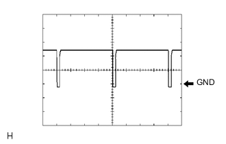
Waveform 1:
Item Content Terminal No. G36-2 (SOL+) - Body ground Tool Setting 5 V/DIV., 500 μs/DIV. Vehicle Condition
-
Engine running
-
"A/C" switch on
-
Blower switch: LO
-
-
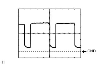
Waveform 2:
Item Content Terminal No. G36-22 (BLW) - Body ground Tool Setting 1 V/DIV., 500 μs/DIV. Vehicle Condition
-
Engine switch on (IG)
-
Blower switch: LO
-
-
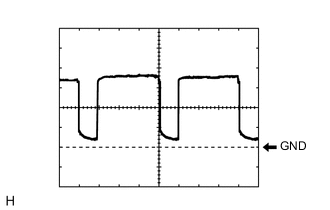
Waveform 3:
Item Content Terminal No. G38-26 (BLWH) - Body ground Tool Setting 2 V/DIV., 500 μs/DIV. Vehicle Condition
-
Engine switch on (IG)
-
Blower switch: LO
-
-
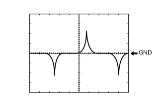
Waveform 4:
Item Content Terminal No. G36-8 (LOCK) - Body ground Tool Setting 200 mV/DIV., 10 ms./DIV. Vehicle Condition
-
Engine running
-
"A/C" switch on
-
Blower switch: LO
-
-
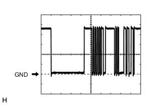
Waveform 5:
Item Content Terminal No. z1-3 (BUS) - z1-2 (BUSG)
G38-1 (RBUS) - G38-25 (RBUG)
Tool Setting 2 V/DIV., 2 ms./DIV. Vehicle Condition Engine switch on (IG)
-
-
AIR CONDITIONING CONTROL ASSEMBLY
-
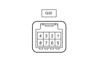
Disconnect the G30 air conditioning control assembly connector.
-
Measure the resistance and voltage, and check for waveform according to the value(s) in the table below.
Terminal No.
(Symbol)
Wiring Color Terminal Description Condition Specified Condition G30-3 (LIN1) - Body ground BE - Body ground LIN communication signal Engine switch on (IG) Pulse generation G30-4 (GND) - Body ground BR - Body ground Ground Always Below 1 Ω G30-5 (IG+) - Body ground B - Body ground Power source (IG) Engine switch on (IG) 10.5 to 16 V Engine switch off Below 1 V
-
-
INTEGRATION CONTROL AND PANEL ASSEMBLY
-
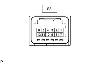
Disconnect the S8 integration control and panel assembly connector.
-
Measure the resistance and voltage, and check for waveform according to the value(s) in the table below.
Terminal No.
(Symbol)
Wiring Color Terminal Description Condition Specified Condition S8-5 (RLIN) - Body ground Y - Body ground LIN communication signal Engine switch on (IG) Pulse generation S8-7 (IG) - Body ground W - Body ground Power source (IG) Engine switch on (IG) 9.5 to 14 V Engine switch off Below 1 V S8-12 (GND) - Body ground W-B - Body ground Ground Always Below 1 Ω
-