SEAT BELT WARNING SYSTEM Driver Side Seat Belt Warning Light does not Operate
DESCRIPTION
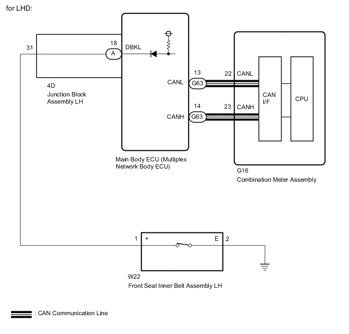
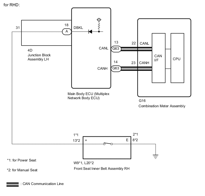
When the engine switch is turned on (IG), the main body ECU (multiplex network body ECU) transmits front seat inner belt (driver seat) state signals to the combination meter assembly through the CAN. If the driver side seat belt is not fastened, the combination meter assembly blinks the seat belt warning light. If the seat belt is fastened, the warning light goes off.
Tech Tips
The front seat belt warning light on the combination meter assembly is used for both the driver side seat and front passenger side seat.
WIRING DIAGRAM
CAUTION / NOTICE / HINT
Note
-
The seat belt warning system uses a CAN communication system. Inspect the communication function by following How to Proceed with troubleshooting.
Troubleshoot the seat belt warning system after confirming that the communication system is functioning properly.
-
As the door control battery is installed between the vehicle battery and main body ECU (multiplex network body ECU), first perform the inspections in On-Vehicle Inspection to confirm that there are no malfunctions in the power source circuit for the main body ECU (multiplex network body ECU) before performing this troubleshooting procedure.
-
Before replacing the main body ECU (multiplex network body ECU), refer to Service Bulletin.
-
When replacing the combination meter assembly, make sure to replace it with a new one.
PROCEDURE
-
PERFORM ACTIVE TEST USING GTS (DRIVER SIDE SEAT BELT)
-
Connect the GTS to the DLC3.
-
Turn the engine switch on (IG).
-
Turn the GTS on.
-
Enter the following menus: Body Electrical / Combination Meter / Active Test.
-
Perform the Active Test according to the display on the GTS.
Body Electrical > Combination Meter > Active TestTester Display Measurement Item Control Range Diagnostic Note Driver Side Seat Belt Seat belt warning light OFF/ON -
Body Electrical > Combination Meter > Active TestTester Display Driver Side Seat Belt OK The seat belt warning light on the combination meter assembly operates normally. Result Proceed to OK NG
NG 
REPLACE COMBINATION METER ASSEMBLY Click here
OK 
-
-
READ VALUE USING GTS (D SEAT BUCKLE SW)
-
Connect the GTS to the DLC3.
-
Turn the engine switch on (IG).
-
Turn the GTS on.
-
Enter the following menus: Body Electrical / Main Body / Data List.
-
Read the Data List according to the display on the GTS.
Body Electrical > Main Body > Data ListTester Display Measurement Item Range Normal Condition Diagnostic Note D Seat Buckle SW Driver side seat belt buckle signal ON or OFF ON: Driver side seat belt fastened
OFF: Driver side seat belt unfastened
-
Body Electrical > Main Body > Data ListTester Display D Seat Buckle SW Result Result Proceed to ON or OFF is displayed on the GTS screen according to the driver side seat belt condition A ON or OFF is not displayed normally on the GTS screen according to the driver side seat belt condition (for LHD) B ON or OFF is not displayed normally on the GTS screen according to the driver side seat belt condition (for RHD) C
A
REPLACE MAIN BODY ECU (MULTIPLEX NETWORK BODY ECU) Click here
C 
INSPECT FRONT SEAT INNER BELT ASSEMBLY RH Click here
B
-
-
INSPECT FRONT SEAT INNER BELT ASSEMBLY LH
-
Remove the front seat inner belt assembly LH.
for Manual Seat:
for Power Seat:
Click here
-
Inspect the front seat inner belt assembly LH.
for Manual Seat:
for Power Seat:
Result Proceed to OK NG
NG
REPLACE FRONT SEAT INNER BELT ASSEMBLY LH for Manual Seat: REPLACE FRONT SEAT INNER BELT ASSEMBLY LH Click here
REPLACE FRONT SEAT INNER BELT ASSEMBLY LH for Power Seat: REPLACE FRONT SEAT INNER BELT ASSEMBLY LH Click hereOK
-
-
CHECK HARNESS AND CONNECTOR (FRONT SEAT INNER BELT ASSEMBLY LH - JUNCTION BLOCK ASSEMBLY LH AND BODY GROUND)
-
Disconnect the 4D junction block assembly LH connector.
-
Disconnect the W22 front seat inner belt assembly LH connector.
-
Measure the resistance according to the value(s) in the table below.
Standard Resistance Tester Connection Condition Specified Condition 4D-31 - W22-1(+) Always Below 1 Ω W22-2 (E) - Body ground Always Below 1 Ω 4D-31 - Body ground Always 10 kΩ or higher Result Proceed to OK NG
NG
REPAIR OR REPLACE HARNESS OR CONNECTOR
OK
-
-
INSPECT JUNCTION BLOCK ASSEMBLY LH
-
Remove the junction block assembly LH.
-
Remove the main body ECU (multiplex network body ECU) from the junction block assembly LH.
-
Measure the resistance according to the value(s) in the table below.
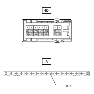
Standard Resistance Tester Connection Condition Specified Condition A-18 (DBKL) - 4D-31 Always Below 1 Ω Result Proceed to OK NG
OK
REPLACE MAIN BODY ECU (MULTIPLEX NETWORK BODY ECU) Click here
NG
REPLACE JUNCTION BLOCK ASSEMBLY LH Click here
-
-
INSPECT FRONT SEAT INNER BELT ASSEMBLY RH
-
Remove the front seat inner belt assembly RH.
for Manual Seat:
for Power Seat:
-
Inspect the front seat inner belt assembly RH.
for Manual Seat:
for Power Seat:
Result Proceed to OK NG
NG
REPLACE FRONT SEAT INNER BELT ASSEMBLY RH for Manual Seat: REPLACE FRONT SEAT INNER BELT ASSEMBLY RH Click here
REPLACE FRONT SEAT INNER BELT ASSEMBLY RH for Power Seat: REPLACE FRONT SEAT INNER BELT ASSEMBLY RH Click hereOK
-
-
CHECK HARNESS AND CONNECTOR (FRONT SEAT INNER BELT ASSEMBLY RH - JUNCTION BLOCK ASSEMBLY LH AND BODY GROUND)
-
Disconnect the 4D junction block assembly LH connector.
-
Disconnect the W9*1 or L20*2 front seat inner belt assembly RH connector.
-
*1: for Power Seat
-
*2: for Manual Seat
-
-
Measure the resistance according to the value(s) in the table below.
Standard Resistance for Power Seat Tester Connection Condition Specified Condition 4D-31 - W9-1(+) Always Below 1 Ω W9-2(E) - Body ground Always Below 1 Ω 4D-31 - Body ground Always 10 kΩ or higher for Manual Seat Tester Connection Condition Specified Condition 4D-31 - L20-13(+) Always Below 1 Ω L20-8(E) - Body ground Always Below 1 Ω 4D-31 - Body ground Always 10 kΩ or higher Result Proceed to OK NG
NG
REPAIR OR REPLACE HARNESS OR CONNECTOR
OK
-
-
INSPECT JUNCTION BLOCK ASSEMBLY LH
-
Remove the junction block assembly LH.
-
Remove the main body ECU (multiplex network body ECU) from the junction block assembly LH.
-
Measure the resistance according to the value(s) in the table below.
Standard Resistance Tester Connection Condition Specified Condition A-18 (DBKL) - 4D-31 Always Below 1 Ω Result Proceed to OK NG
OK
REPLACE MAIN BODY ECU (MULTIPLEX NETWORK BODY ECU) Click here
NG
REPLACE JUNCTION BLOCK ASSEMBLY LH Click here
-