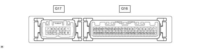
SEAT BELT WARNING SYSTEM TERMINALS OF ECU
-
CHECK COMBINATION METER ASSEMBLY
-
Disconnect the G16 combination meter assembly connector.
-
Measure the resistance and voltage according to the value(s) in the table below.
Tester Connection Wiring Color Terminal Description Condition Specified Condition G16-2 (IG+) - Body ground G - Body ground IG power supply Engine switch on (IG) → off 11 to 14 V → Below 1 V*1 10.5 to 16 V → Below 1 V*2 G16-1 (B) - Body ground P - Body ground Battery power supply Always 11 to 14 V G16-21 (ES) - Body ground BR - Body ground Ground Always Below 1 Ω
-
*1: w/o Stop and Start System
-
*2: w/ Stop and Start System
-
-
Reconnect the G16 combination meter assembly connector.
-
Measure the voltage according to the value(s) in the table below.
Tester Connection Wiring Color Terminal Description Condition Specified Condition G16-24 (PODS) - Body ground R - Body ground Occupant detection sensor signal Engine switch on (IG), occupant not in passenger seat → occupant in passenger seat 11 to 14 V → Below 1 V G16-30 (PBKL) - Body ground G - Body ground Front passenger seat belt buckle switch signal Engine switch on (IG), occupant in passenger seat, and tongue plate not inserted into passenger seat inner belt → tongue plate inserted Below 1 V → 11 to 14 V
-
-
CHECK MAIN BODY ECU (MULTIPLEX NETWORK BODY ECU) AND JUNCTION BLOCK ASSEMBLY LH

*A Main Body ECU (Multiplex Network Body ECU) with 2 connectors - - *1 Main Body ECU (Multiplex Network Body ECU) - - 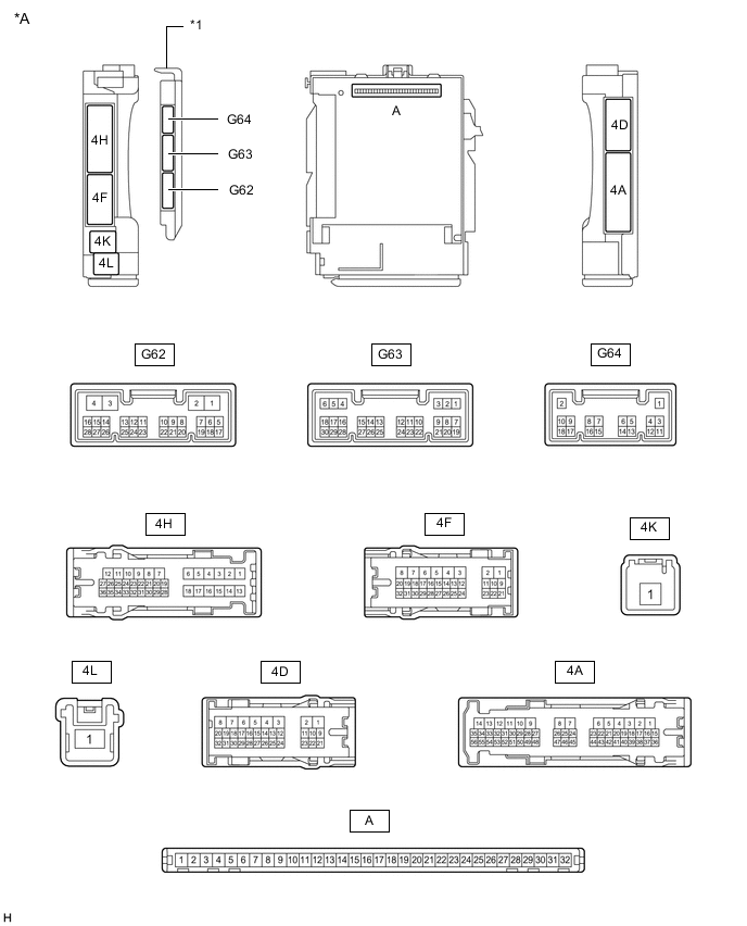
*A Main Body ECU (Multiplex Network Body ECU) with 3 connectors - - *1 Main Body ECU (Multiplex Network Body ECU) - -
-
Remove the main body ECU (multiplex network body ECU) from the junction block assembly LH.
-
Reconnect the junction block assembly LH connectors.
-
Measure the resistance and voltage according to the value(s) in the table below.
Tester Connection Wiring Color Terminal Description Condition Specified Condition A-11 (GND1) - Body ground - Ground Always Below 1 Ω A-30 (ACC) - Body ground - ACC power supply Engine switch on (ACC) → off 11 to 14 V → Below 1 V A-31 (BECU) - Body ground - Battery power supply Always 11 to 14 V A-32 (IG) - Body ground - IG power supply Engine switch on (IG) → off 11 to 14 V → Below 1 V -
Install the main body ECU (multiplex network body ECU) to the junction block assembly LH.
-
Measure the voltage according to the value(s) in the table below.
Tester Connection Wiring Color Terminal Description Condition Specified Condition 4D-31 - Body ground L - Body ground Driver seat belt buckle switch signal Engine switch on (IG), driver seat belt unfastened → fastened Below 1 V → 11 to 14 V
-