REAR CONTROL SWITCH INSPECTION
PROCEDURE
-
INSPECT REAR POWER SEAT SWITCH LH
-
Check rear power seat switch LH.
-
Measure the voltage according to the value(s) in the table below.
Tech Tips
As the circuit has a diode, perform the measurement in diode mode.
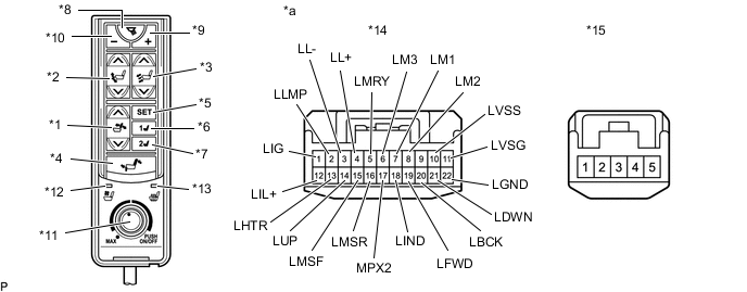
*1 Reclining Switch *2 Ottoman Switch (Open/Close) *3 Ottoman Switch (Expansion/Contraction) *4 Return Switch *5 SET Switch *6 M1 Switch *7 M2 Switch *8 Reading Light On/Off Switch *9 Reading Light Adjustment Switch (+) *10 Reading Light Adjustment Switch (-) *11 Heated and Ventilated Seat Main Switch *12 Seat Blower Indicator Light *13 Seat Heater Indicator Light *14 Connector A *15 Connector B - - *a Component without harness connected
(Rear Power Seat Switch LH)
- - Standard Voltage Reclining Switch Tester Connection Switch Condition Specified Condition Positive (+) tester lead - A5 (LMRY)
Negative (-) tester lead - A8 (LM2)
Reclining switch (front) pressed 1.0 V or less Positive (+) tester lead - A5 (LMRY)
Negative (-) tester lead - A14 (LUP)
Reclining switch (rear) pressed Ottoman Switch (Open/Close) Tester Connection Switch Condition Specified Condition Positive (+) tester lead - A6 (LM3)
Negative (-) tester lead - A8 (LM2)
Ottoman switch (open) pressed 1.0 V or less Positive (+) tester lead - A6 (LM3)
Negative (-) tester lead - A14 (LUP)
Ottoman switch (close) pressed Ottoman Switch (Expansion/Contraction) Tester Connection Switch Condition Specified Condition Positive (+) tester lead - A7 (LM1)
Negative (-) tester lead - A8 (LM2)
Ottoman switch (expansion) pressed 1.0 V or less Positive (+) tester lead - A7 (LM1)
Negative (-) tester lead - A14 (LUP)
Ottoman switch (contraction) pressed Return Switch Tester Connection Switch Condition Specified Condition Positive (+) tester lead - A5 (LMRY)
Negative (-) tester lead - A16 (LMSR)
Return switch pressed 1.0 V or less Seat Memory Switch Tester Connection Switch Condition Specified Condition Positive (+) tester lead - A5 (LMRY)
Negative (-) tester lead - A15 (LMSF)
SET switch pressed 1.0 V or less Positive (+) tester lead - A6 (LM3)
Negative (-) tester lead - A15 (LMSF)
M1 switch pressed Positive (+) tester lead - A7 (LM1)
Negative (-) tester lead - A15 (LMSF)
M2 switch pressed If the result is not as specified, replace the rear power seat switch LH.
-
Measure the resistance according to the value(s) in the table below.
Standard Resistance Reading Light Switch Tester Connection Switch Condition Specified Condition A2 (LLMP) - A22 (LGND) Reading light on/off switch pressed Below 50 Ω A4 (LL+) - A22 (LGND) Reading light adjustment switch (+) pressed A3 (LL-) - A22 (LGND) Reading light adjustment switch (-) pressed Heated and Ventilated Seat Main Switch Tester Connection Switch Condition Specified Condition A13 (LHTR) - A22 (LGND) Heated and ventilated seat main switch pressed Below 1 Ω A10 (LVSS) - A11 (LVSG) Seat ventilation MAX to seat heater MAX 1 Ω to 5 kΩ If the result is not as specified, replace the rear power seat switch LH.
-
Measure the resistance according to the value(s) in the table below.
Standard Resistance Tester Connection Switch Condition Specified Condition A1 (LIG) - B3 Always Below 1 Ω A19 (LFWD) - B5 A20 (LBCK) - B4 A21 (LDWN) - B2 A22 (LGND) - B1 If the result is not as specified, replace the rear power seat switch LH.
-
Apply battery voltage to the switch connector and check that the rear power seat switch LH illuminates.
OK Condition Specified Condition Battery positive (+) - A12 (LIL+)
Battery negative (-) - A22 (LGND)
Illumination illuminates If the result is not as specified, replace the rear power seat switch LH.
-
Apply battery voltage to the switch connector and check that the rear power seat switch LH indicator illuminates.
OK Condition Specified Condition Battery positive (+) - A1 (LIG)
Battery negative (-) - A18 (LIND)
Seat blower indicator light illuminates Battery positive (+) - A1 (LIG)
Battery negative (-) - A17 (MPX2)
Seat heater indicator light illuminates If the result is not as specified, replace the rear power seat switch LH.
-
-
-
INSPECT REAR POWER SEAT SWITCH RH
-
Check rear power seat switch RH.
-
Measure the voltage according to the value(s) in the table below.
Tech Tips
As the circuit has a diode, perform the measurement in diode mode.
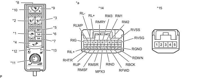
*1 Reclining Switch *2 Ottoman Switch (Open/Close) *3 Ottoman Switch (Expansion/Contraction) *4 Return Switch *5 SET Switch *6 M1 Switch *7 M2 Switch *8 Reading Light On/Off Switch *9 Reading Light Adjustment Switch (+) *10 Reading Light Adjustment Switch (-) *11 Heated and Ventilated Seat Main Switch *12 Seat Blower Indicator Light *13 Seat Heater Indicator Light *14 Connector A *15 Connector B - - *a Component without harness connected
(Rear Power Seat Switch RH)
- - Standard Voltage Reclining Switch Tester Connection Switch Condition Specified Condition Positive (+) tester lead - A5 (RMRY)
Negative (-) tester lead - A8 (RM2)
Reclining switch (front) pressed 1.0 V or less Positive (+) tester lead - A5 (RMRY)
Negative (-) tester lead - A14 (RUP)
Reclining switch (rear) pressed Ottoman Switch (Open/Close) Tester Connection Switch Condition Specified Condition Positive (+) tester lead - A6 (RM3)
Negative (-) tester lead - A8 (RM2)
Ottoman switch (open) pressed 1.0 V or less Positive (+) tester lead - A6 (RM3)
Negative (-) tester lead - A14 (RUP)
Ottoman switch (close) pressed Ottoman Switch (Expansion/Contraction) Tester Connection Switch Condition Specified Condition Positive (+) tester lead - A7 (RM1)
Negative (-) tester lead - A8 (RM2)
Ottoman switch (expansion) pressed 1.0 V or less Positive (+) tester lead - A7 (RM1)
Negative (-) tester lead - A14 (RUP)
Ottoman switch (contraction) pressed Return Switch Tester Connection Switch Condition Specified Condition Positive (+) tester lead - A5 (RMRY)
Negative (-) tester lead - A16 (RMSR)
Return switch pressed 1.0 V or less Seat Memory Switch Tester Connection Switch Condition Specified Condition Positive (+) tester lead - A5 (RMRY)
Negative (-) tester lead - A15 (RMSF)
SET switch pressed 1.0 V or less Positive (+) tester lead - A6 (RM3)
Negative (-) tester lead - A15 (RMSF)
M1 switch pressed Positive (+) tester lead - A7 (RM1)
Negative (-) tester lead - A15 (RMSF)
M2 switch pressed If the result is not as specified, replace the rear power seat switch RH.
-
Measure the resistance according to the value(s) in the table below.
Standard Resistance Reading Light Switch Tester Connection Switch Condition Specified Condition A2 (RLMP) - A22 (RGND) Reading light on/off switch pressed Below 50 Ω A4 (RL+) - A22 (RGND) Reading light adjustment switch (+) pressed A3 (RL-) - A22 (RGND) Reading light adjustment switch (-) pressed Heated and Ventilated Seat Main Switch Tester Connection Switch Condition Specified Condition A13 (RHTR) - A22 (RGND) Heated and ventilated seat main switch pressed Below 1 Ω A10 (RVSS) - A11 (RVSG) Seat ventilation MAX to seat heater MAX 1 Ω to 5 kΩ If the result is not as specified, replace the rear power seat switch RH.
-
Measure the resistance according to the value(s) in the table below.
Standard Resistance Tester Connection Switch Condition Specified Condition A1 (RIG) - B3 Always Below 1 Ω A19 (RFWD) - B5 A20 (RBCK) - B4 A21 (RDWN) - B2 A22 (RGND) - B1 If the result is not as specified, replace the rear power seat switch RH.
-
Apply battery voltage to the switch connector and check that the rear power seat switch RH illuminates.
OK Condition Specified Condition Battery positive (+) - A12 (RIL+)
Battery negative (-) - A22 (RGND)
Illumination illuminates If the result is not as specified, replace the rear power seat switch RH.
-
Apply battery voltage to the switch connector and check that the rear power seat switch RH indicator illuminates.
OK Condition Specified Condition Battery positive (+) - A1 (RIG)
Battery negative (-) - A18 (RIND)
Seat blower indicator light illuminates Battery positive (+) - A1 (RIG)
Battery negative (-) - A17 (MPX3)
Seat heater indicator light illuminates If the result is not as specified, replace the rear power seat switch RH.
-
-