SEAT RAIL INSTALLATION
PROCEDURE
-
INSTALL REAR SEAT TRACK ASSEMBLY LH
-
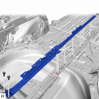
for Manual Captain Seat:
-
Install the rear seat track assembly LH by installing the 7 nuts to the bottom of the vehicle and the 2 bolts to the inside of the vehicle.
- Torque:
- for Nut
- 72 N*m { 734 kgf*cm, 53 ft.*lbf }
- for Bolt
- 42 N*m { 428 kgf*cm, 31 ft.*lbf }
-
-
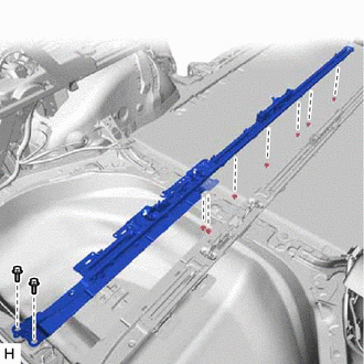
for Power Captain Seat:
-
Install the rear seat track assembly LH by installing the 7 nuts to the bottom of the vehicle and the 2 bolts to the inside of the vehicle.
- Torque:
- for Nut
- 72 N*m { 734 kgf*cm, 53 ft.*lbf }
- for Bolt
- 42 N*m { 428 kgf*cm, 31 ft.*lbf }
-
-
-
INSTALL REAR NO. 1 SEAT TRACK ASSEMBLY RH
-
for Manual Captain Seat:
Tech Tips
Install using the same procedure described for the rear seat track assembly LH side.
-
for Power Captain Seat:
Tech Tips
Install using the same procedure described for the rear seat track assembly LH side.
-
-
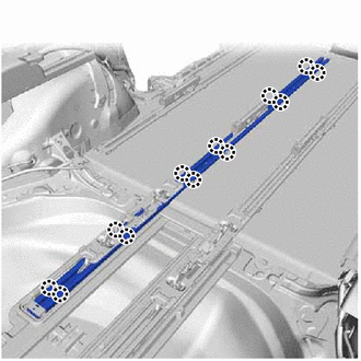
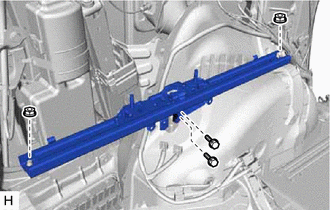
INSTALL REAR OUTER SEAT TRACK ASSEMBLY LH
-
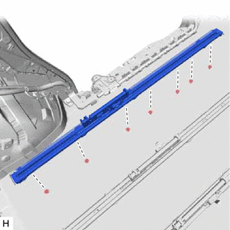
for Manual Captain Seat:
-
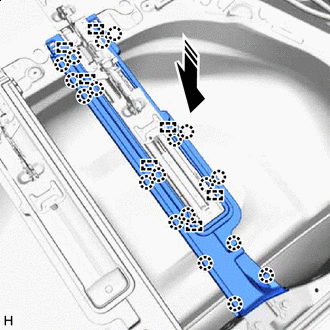
Install the rear outer seat track assembly LH by installing the 7 nuts to the bottom of the vehicle.
- Torque:
- 72 N*m { 734 kgf*cm, 53 ft.*lbf }
-
-
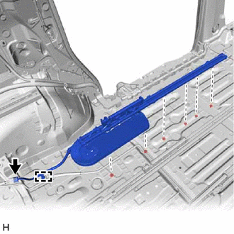
for Power Captain Seat:
-
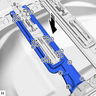
Install the rear outer seat track assembly LH by installing the 6 nuts to the bottom of the vehicle.
- Torque:
- 72 N*m { 734 kgf*cm, 53 ft.*lbf }
-
Attach the clamp to connect the wire harness.
-
Connect the connector.
-
Return the rear floor mat assembly RH to its original position.
-
-
-
INSTALL REAR OUTER SEAT TRACK ASSEMBLY RH
-
for Manual Captain Seat:
Tech Tips
Use the same procedure as for the LH side.
-
for Power Captain Seat:
Tech Tips
Use the same procedure as for the LH side.
-
-
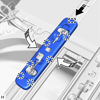
INSTALL CENTER NO. 2 FLOOR HEAT INSULATOR SUB-ASSEMBLY
Tech Tips
Perform this procedure when removing and installing the rail on the inner side.
-
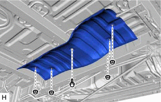
Install the center No. 2 floor heat insulator sub-assembly with the bolt and 4 nuts.
- Torque:
- for Bolt
- 9.0 N*m { 92 kgf*cm, 80 in.*lbf }
- for Nut
- 6.0 N*m { 61 kgf*cm, 53 in.*lbf }
-
-
INSTALL EXHAUST FORKED PIPE SUB-ASSEMBLY (TWC: Rear Catalyst) (for 2GR-FKS)
Tech Tips
Perform this procedure when removing and installing the rail on the inner side.
-
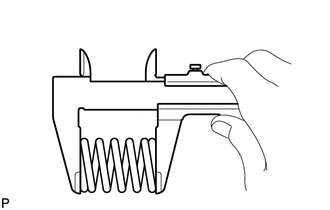
Using a vernier caliper, measure the free length of the 2 compression springs.
Standard Length 43.0 mm (1.69 in.) Minimum Free Length 41.5 mm (1.63 in.) If the free length is less than the minimum, replace the compression spring.
-
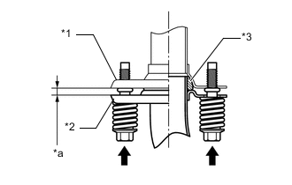
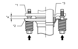
Temporarily install a new exhaust pipe gasket to the front No. 3 exhaust pipe sub-assembly.
-
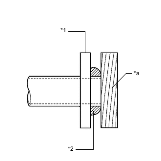
*1 Front No. 3 Exhaust Pipe Sub-assembly *2 Exhaust Pipe Gasket *a Wooden Block Using a plastic-faced hammer and wooden block, tap in the gasket until its surface is flush with the front No. 3 exhaust pipe sub-assembly.
Note
-
Be sure to install the gasket in the correct direction.
-
Do not reuse the gasket.
-
Do not damage the gasket.
-
Do not push in the gasket by using the exhaust pipes when connecting them.
-
-
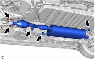
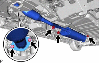
Connect the exhaust forked pipe sub-assembly (TWC: Rear Catalyst) to the 3 exhaust pipe supports.
-
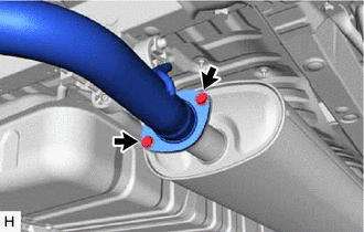
Install the exhaust forked pipe sub-assembly (TWC: Rear Catalyst) to the front No. 3 exhaust pipe sub-assembly with the 2 bolts and 2 compression springs.
- Torque:
- 43 N*m { 438 kgf*cm, 32 ft.*lbf }
Tech Tips
After installation, check that the space between the flanges of the exhaust forked pipe sub-assembly (TWC: Rear Catalyst) and front No. 3 exhaust pipe sub-assembly is consistent front-to-rear and left-to-right.
*1 Exhaust Forked Pipe Sub-assembly (TWC: Rear Catalyst) *2 Front No. 3 Exhaust Pipe Sub-assembly *3 Exhaust Pipe Gasket *a Space between Flanges: 8.5 mm (0.335 in.) -
Temporarily install a new exhaust pipe gasket to the exhaust forked pipe sub-assembly (TWC: Rear Catalyst).
-
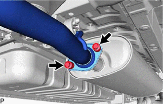
Install the tail exhaust pipe assembly to the exhaust forked pipe sub-assembly (TWC: Rear Catalyst) with the 2 bolts.
- Torque:
- 43 N*m { 438 kgf*cm, 32 ft.*lbf }
-
-
INSTALL CENTER EXHAUST PIPE ASSEMBLY (TWC: Rear Catalyst) (for 2AR-FE)
Tech Tips
Perform this procedure when removing and installing the rail on the inner side.
-
Install a new exhaust pipe gasket to the front exhaust pipe assembly.
-
Connect the center exhaust pipe assembly (TWC: Rear Catalyst) to the 3 exhaust pipe supports.
-
Install the center exhaust pipe assembly (TWC: Rear Catalyst) to the front exhaust pipe assembly with the 2 bolts.
- Torque:
- 43 N*m { 438 kgf*cm, 32 ft.*lbf }
-
Using a vernier caliper, measure the free length of the compression springs.
Standard Length 40.0 mm (1.57 in.) Minimum Free Length 38.5 mm (1.52 in.) If the free length is less than the minimum, replace the compression spring.
-
Temporarily install a new exhaust pipe gasket to the center exhaust pipe assembly (TWC: Rear Catalyst).
-
*1 Center Exhaust Pipe Assembly (TWC: Rear Catalyst) *2 Exhaust Pipe Gasket *a Wooden Block Using a plastic-faced hammer and wooden block, tap in the exhaust pipe gasket until its surface is flush with the center exhaust pipe assembly (TWC: Rear Catalyst).
Note
-
Be sure to install the gasket in the correct direction.
-
Do not reuse the gasket.
-
Do not damage the gasket.
-
Do not push in the gasket by using the exhaust pipes when connecting them.
-
-
Install the tail exhaust pipe assembly to the center exhaust pipe assembly (TWC: Rear Catalyst) with the 2 bolts and 2 compression springs.
- Torque:
- 43 N*m { 438 kgf*cm, 32 ft.*lbf }
Tech Tips
After installation, check that the space between the flanges of the center exhaust pipe assembly (TWC: Rear Catalyst) and tail exhaust pipe assembly is consistent front-to-rear and left-to-right.
*1 Center Exhaust Pipe Assembly (TWC: Rear Catalyst) *2 Tail Exhaust Pipe Assembly *3 Exhaust Pipe Gasket *a Space between Flanges: 6.5 mm (0.256 in.)
-
-
INSTALL FUEL TANK ASSEMBLY
Tech Tips
Perform this procedure when removing and installing the rail on the inner side.
-
for 2AR-FE:
-
for 2GR-FKS:
-
-
INSTALL NO. 1 DECK RAIL COVER
-

Install in this Direction Insert the claw and guide to install the No. 1 deck rail cover.
-
-
INSTALL NO. 2 DECK RAIL COVER
-
Install in this Direction Insert the claw and guide to install the No. 2 deck rail cover.
-
-
INSTALL DECK RAIL COVER
-
Install in this Direction Insert the claw and guide to install the deck rail cover.
-
-
INSTALL REAR UPPER NO. 3 FLOOR BOARD PLATE
-
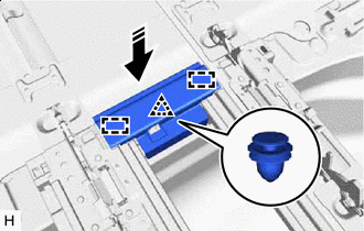
Install in this Direction Attach the clip and insert the guide to install the rear upper No. 3 floor board plate.
-
-
INSTALL LOWER SEAT TRACK RAIL PROTECTOR (for Captain Seat Type)
Tech Tips
Use the same procedure for the opposite side.
-
Attach the claw to install the 2 lower seat track rail protectors.
-
-
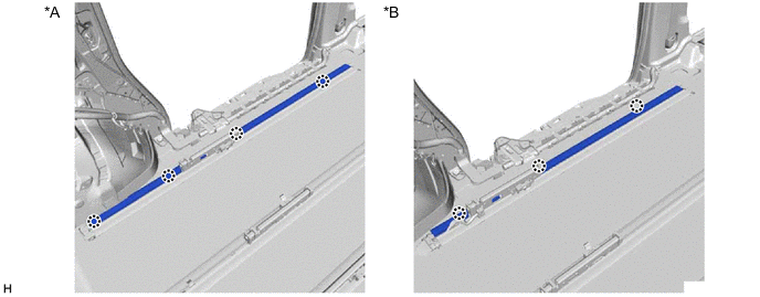
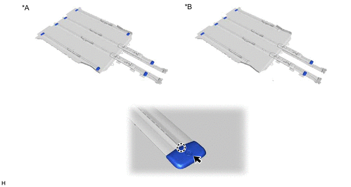
INSTALL LOWER NO. 2 SEAT TRACK RAIL PROTECTOR
Tech Tips
Use the same procedure for the opposite side.
-
Attach the claw to install the lower No. 2 seat track rail protector.
*A for Manual Captain Seat *B for Power Captain Seat
-
-
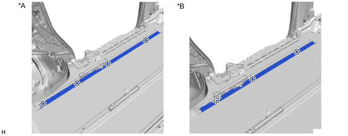
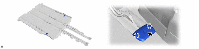
INSTALL LOWER NO. 1 SEAT TRACK RAIL PROTECTOR
Tech Tips
Use the same procedure for the opposite side.
-
Attach the claw to install the lower No. 1 seat track rail protector.
*A for Manual Captain Seat *B for Power Captain Seat
-
-
INSTALL NO. 4 FLOOR CARPET MOULDING (for Power Captain Seat)
-
Attach the claw and clip to install the 2 No. 4 floor carpet mouldings.
-
-
INSTALL NO. 3 FLOOR CARPET MOULDING
-
for Manual Captain Seat:
Attach the claw and clip to install the 8 No. 3 floor carpet mouldings.
*A for Manual Captain Seat *B for Power Captain Seat -
for Power Captain Seat:
Attach the claw and clip to install the 6 No. 3 floor carpet mouldings.
-
-
INSTALL REAR SEAT LOCK STRIKER COVER
Tech Tips
Use the same procedure for the opposite side.
-
Install in this Direction (1) 
Install in this Direction (2) Push in installation direction (1) shown in the illustration to insert the guide.
-
Press in installation direction (2) shown in the illustration to attach the claw to install the rear seat lock striker cover.
-
-
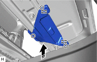
INSTALL REAR NO. 2 SEAT TRACK ASSEMBLY RH
-

Install the rear No. 2 seat track assembly RH with the 2 bolts and 2 nuts.
- Torque:
- for Bolt
- 42 N*m { 428 kgf*cm, 31 ft.*lbf }
- Torque:
- for Nut
- 42 N*m { 428 kgf*cm, 31 ft.*lbf }
-
-
INSTALL REAR NO. 2 SEAT TRACK ASSEMBLY LH
-
Install the rear No. 2 seat track assembly LH with the 2 bolts and 2 nuts.
- Torque:
- for Bolt
- 42 N*m { 428 kgf*cm, 31 ft.*lbf }
- Torque:
- for Nut
- 42 N*m { 428 kgf*cm, 31 ft.*lbf }
-
-
INSTALL PARKING BRAKE ECU ASSEMBLY
-
INSTALL REAR QUARTER TRIM PANEL ASSEMBLY RH
-
INSTALL REAR QUARTER TRIM PANEL ASSEMBLY LH
-
INSTALL ROPE HOOK ASSEMBLY
-
INSTALL NO. 1 LUGGAGE COMPARTMENT TRIM HOOK
-
INSTALL NO. 2 LUGGAGE COMPARTMENT TRIM HOOK
-
INSTALL DECK SIDE GARNISH LH
-
INSTALL DECK SIDE GARNISH RH
-
INSTALL REAR UPPER NO. 1 FLOOR BOARD PLATE
-
INSTALL REAR UPPER NO. 2 FLOOR BOARD PLATE
-
INSTALL BACK DOOR SCUFF PLATE
-
INSTALL UTILITY BOX SUB-ASSEMBLY
-
INSTALL REAR NO. 3 FLOOR BOARD ASSEMBLY
-
INSTALL REAR NO. 2 FLOOR BOARD ASSEMBLY
-
INSTALL REAR NO. 1 FLOOR BOARD ASSEMBLY
-
INSTALL REAR DOOR SCUFF PLATE RH
-
INSTALL REAR DOOR SCUFF PLATE LH
-
INSTALL REAR SEAT TRACK SLIDE STOPPER
-
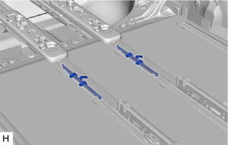
Install the 2 rear seat track slide stoppers.
-
-
INSTALL REAR SEAT STOPPER
Tech Tips
Use the same procedure for the opposite side.
-
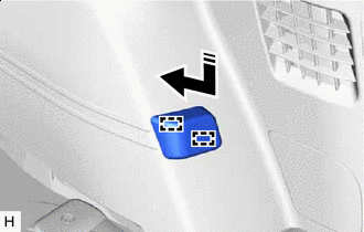
Install in this Direction Push as shown in the illustration to insert the guide to install the rear seat stopper.
-
-
INSTALL REAR NO. 2 SEAT ASSEMBLY RH
-
INSTALL REAR NO. 2 SEAT ASSEMBLY LH
-
INSTALL REAR NO. 1 SEAT ASSEMBLY RH
-
for Manual Captain Seat:
-
for Power Captain Seat with Memory:
-
for Power Captain Seat without Memory:
-
-
INSTALL REAR NO. 1 SEAT ASSEMBLY LH
-
for Manual Captain Seat:
-
for Power Captain Seat with Memory:
-
for Power Captain Seat without Memory:
-
-
CONNECT CABLE TO NEGATIVE BATTERY TERMINAL
Note
When disconnecting the cable, some systems need to be initialized after the cable is reconnected.
-
CHECK SRS WARNING LIGHT
-
INSPECT FOR EXHAUST GAS LEAK
If gas is leaking, tighten the areas necessary to stop the leak. Replace damaged parts as necessary.
-
Perform Inspection After Repair after repairing an exhaust gas leak.
-
for 2AR-FE:
-
for 2GR-FKS:
-
-