REAR POWER SEAT MOTOR ASSEMBLY INSPECTION
CAUTION / NOTICE / HINT
Tech Tips
Use the same procedure for the RH and LH sides.
PROCEDURE
-
INSPECT POWER SEAT MOTOR ASSEMBLY
-
Check that the control lever operates smoothly when the battery is connected to the connector terminal of the power seat motor assembly.
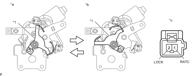
*1 Control Lever - - *a Neutral Position *b Full Stroke Position *c Component without wire harness connected
(Power Seat Motor Assembly)
- - OK Condition Specified Condition Battery positive (+) → Terminal 1 (RATC)
Battery negative (-) → Terminal 2 (LOCK)
Neutral position → full stroke position Battery positive (+) → Terminal 2 (LOCK)
Battery negative (-) → Terminal 1 (RATC)
Full stroke position → neutral position If the result is not as specified, replace the power seat motor assembly.
-
Measure the resistance according to the value(s) in the table below.
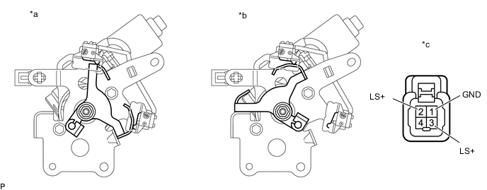
*a Neutral Position *b Full Stroke Position *c Component without wire harness connected
(Power Seat Motor Assembly)
- - Standard Resistance Tester Connection Switch Condition Specified Condition 1 (GND) - 2 (LS+)
1 (GND) - 3 (LS+)
Neutral Position Below 1 Ω 1 (GND) - 2 (LS+) Full Stroke Position 10 kΩ or higher 1 (GND) - 3 (LS+) Below 1 Ω If the result is not as specified, replace the power seat motor assembly.
-