REAR NO. 1 SEAT ASSEMBLY(for Power Captain Seat with Memory) INSPECTION
PROCEDURE
-
INSPECT NO. 1 SEATBACK FRAME SUB-ASSEMBLY LH
-
Check the operation of the reclining motor.
-
Apply battery voltage to the reclining motor connector, and check that the No. 1 seatback frame sub-assembly LH operates smoothly as follows.
Note
-
Connect the battery simultaneously to motor A and motor B to perform an inspection.
-
Do not apply voltage to terminals 2, 5 and 6 of the connector for motor A.
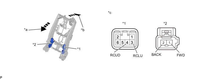
*1 Motor A *2 Motor B *a Forward *b Backward *c Component without wire harness connected
(No. 1 Seatback Frame sub-assembly LH)
- - OK Condition Specified Condition Battery positive (+) → Terminal 3 (RCLU) (Motor A)
Battery negative (-) → Terminal 4 (RCUD) (Motor A)
Forward Battery positive (+) → Terminal 1 (FWD) (Motor B)
Battery negative (-) → Terminal 2 (BACK) (Motor B)
Battery positive (+) → Terminal 4 (RCUD) (Motor A)
Battery negative (-) → Terminal 3 (RCLU) (Motor A)
Backward Battery positive (+) → Terminal 2 (BACK) (Motor B)
Battery negative (-) → Terminal 1 (FWD) (Motor B)
If the result is not as specified, replace the No. 1 seatback frame sub-assembly LH.
-
-
-
-
INSPECT NO. 1 SEATBACK FRAME SUB-ASSEMBLY RH
-
Check the operation of the reclining motor.
-
Apply battery voltage to the reclining motor connector, and check that the No. 1 seatback frame sub-assembly RH operates smoothly as follows.
Note
-
Connect the battery simultaneously to motor A and motor B to perform an inspection.
-
Do not apply voltage to terminals 2, 5 and 6 of the connector for motor A.
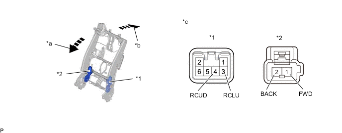
*1 Motor A *2 Motor B *a Forward *b Backward *c Component without wire harness connected
(No. 1 Seatback Frame sub-assembly RH)
- - OK Condition Specified Condition Battery positive (+) → Terminal 3 (RCLU) (Motor A)
Battery negative (-) → Terminal 4 (RCUD) (Motor A)
Forward Battery positive (+) → Terminal 1 (FWD) (Motor B)
Battery negative (-) → Terminal 2 (BACK) (Motor B)
Battery positive (+) → Terminal 4 (RCUD) (Motor A)
Battery negative (-) → Terminal 3 (RCLU) (Motor A)
Backward Battery positive (+) → Terminal 2 (BACK) (Motor B)
Battery negative (-) → Terminal 1 (FWD) (Motor B)
If the result is not as specified, replace the No. 1 seatback frame sub-assembly RH.
-
-
-
-
INSPECT REAR LOWER INNER RECLINING ADJUSTER ARM SUB-ASSEMBLY LH
-
Check the operation of the ottoman motor.
-
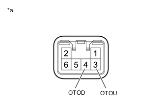
*a Component without wire harness connected
(Rear Lower Inner Reclining Adjuster Arm Sub-assembly LH)
Apply battery voltage to the ottoman motor connector, and check that the rear lower inner reclining adjuster arm sub-assembly LH operates smoothly as follows.
Note
Do not apply voltage to terminals 2, 5 and 6 of the connector.
OK Condition Specified Condition Battery positive (+) → Terminal 3 (OTOU)
Battery negative (-) → Terminal 4 (OTOD)
Open Battery positive (+) → Terminal 4 (OTOD)
Battery negative (-) → Terminal 3 (OTOU)
Close If the result is not as specified, replace the rear lower inner reclining adjuster arm sub-assembly LH.
-
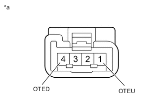
*a Component without wire harness connected
(Rear Lower Inner Reclining Adjuster Arm Sub-assembly LH)
Apply battery voltage to the ottoman motor connector, and check that the rear lower inner reclining adjuster arm sub-assembly LH operates smoothly as follows.
Note
Do not apply voltage to terminals 2 and 3 of the connector.
OK Condition Specified Condition Battery positive (+) → Terminal 1 (OTEU)
Battery negative (-) → Terminal 4 (OTED)
Expansion Battery positive (+) → Terminal 4 (OTED)
Battery negative (-) → Terminal 1 (OTEU)
Contraction If the result is not as specified, replace the rear lower inner reclining adjuster arm sub-assembly LH.
-
-
-
INSPECT REAR LOWER INNER RECLINING ADJUSTER ARM SUB-ASSEMBLY RH
-
Check the operation of the ottoman motor.
-
*a Component without wire harness connected
(Rear Lower Inner Reclining Adjuster Arm Sub-assembly RH)
Apply battery voltage to the ottoman motor connector, and check that the rear lower inner reclining adjuster arm sub-assembly RH operates smoothly as follows.
Note
Do not apply voltage to terminals 2, 5 and 6 of the connector.
OK Condition Specified Condition Battery positive (+) → Terminal 3 (OTOU)
Battery negative (-) → Terminal 4 (OTOD)
Open Battery positive (+) → Terminal 4 (OTOD)
Battery negative (-) → Terminal 3 (OTOU)
Close If the result is not as specified, replace the rear lower inner reclining adjuster arm sub-assembly RH.
-
*a Component without wire harness connected
(Rear Lower Inner Reclining Adjuster Arm Sub-assembly RH)
Apply battery voltage to the ottoman motor connector, and check that the rear lower inner reclining adjuster arm sub-assembly RH operates smoothly as follows.
Note
Do not apply voltage to terminals 2 and 3 of the connector.
OK Condition Specified Condition Battery positive (+) → Terminal 1 (OTEU)
Battery negative (-) → Terminal 4 (OTED)
Expansion Battery positive (+) → Terminal 4 (OTED)
Battery negative (-) → Terminal 1 (OTEU)
Contraction If the result is not as specified, replace the rear lower inner reclining adjuster arm sub-assembly RH.
-
-
-
INSPECT REAR SEAT LOCK OPEN LEVER SUB-ASSEMBLY LH
-
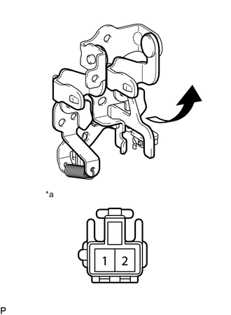
*a Component without harness connected
(Rear Seat Lock Open Lever Sub-assembly LH)
Measure the resistance according to the value(s) in the table below.
Standard Resistance Tester Connection Switch Condition Specified Condition 1 - 2 Operate the lever Below 1 Ω Do not operate the lever 10 kΩ or higher If the result is not as specified, replace the rear seat lock open lever sub-assembly LH.
-
-
INSPECT REAR SEAT LOCK OPEN LEVER SUB-ASSEMBLY RH
-
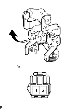
*a Component without harness connected
(Rear Seat Lock Open Lever Sub-assembly RH)
Measure the resistance according to the value(s) in the table below.
Standard Resistance Tester Connection Switch Condition Specified Condition 1 - 2 Operate the lever Below 1 Ω Do not operate the lever 10 kΩ or higher If the result is not as specified, replace the rear seat lock open lever sub-assembly RH.
-
-
INSPECT REAR SEAT CUSHION PAD LH
-
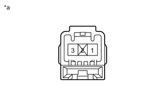
*a Component without harness connected
(Rear Seat Cushion Pad LH)
Measure the resistance according to the value(s) in the table below.
Standard Resistance Tester Connection Condition Specified Condition 1 - 3 Seat occupied Below 100 Ω Seat not occupied 1 MΩ or higher If the result is not as specified, replace the rear seat cushion pad LH.
-
-
INSPECT REAR SEAT CUSHION PAD RH
-
*a Component without harness connected
(Rear Seat Cushion Pad RH)
Measure the resistance according to the value(s) in the table below.
Standard Resistance Tester Connection Condition Specified Condition 1 - 3 Seat occupied Below 100 Ω Seat not occupied 1 MΩ or higher If the result is not as specified, replace the rear seat cushion pad RH.
-