REAR NO. 2 SEAT ASSEMBLY REMOVAL
CAUTION / NOTICE / HINT
Tech Tips
The procedure listed below is for the LH side. Use the same procedure for the LH and RH sides, unless otherwise specified.
PROCEDURE
-
ADJUST REAR NO. 2 SEAT ASSEMBLY LH
-
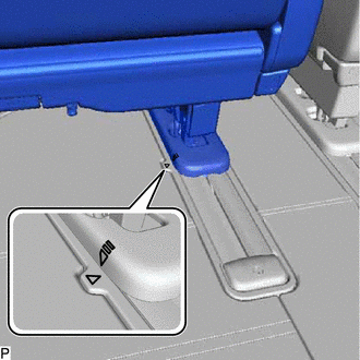
Adjust the position of the rear No. 2 seat assembly LH so that the alignment marks are as shown in the illustration.
-
-
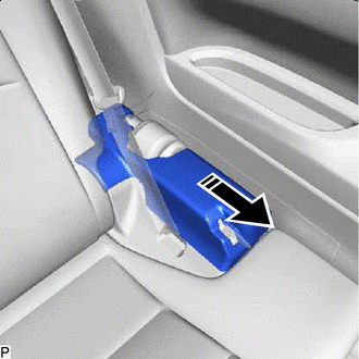
REMOVE RECLINING ADJUSTER RELEASE HANDLE LH
-
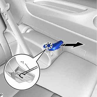
*1 Protective Tape 
Remove in this Direction Make sure the handle is pulled up, and then using a thin-bladed screwdriver with its tip wrapped with protective tape, detach the claw and remove the reclining adjuster release handle LH.
-
-
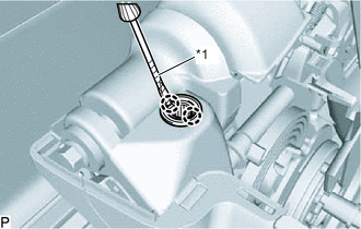
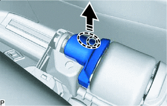
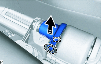
REMOVE SEAT TRACK UPPER RAIL COVER LH
-
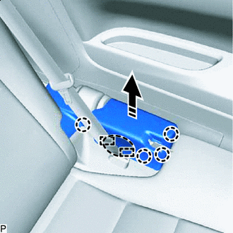

Place hand here Remove in this Direction Move the part in the direction indicated by the arrow shown in the illustration to detach the claw and guide.
-
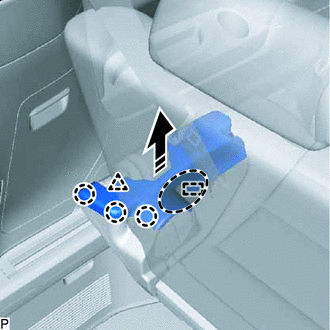
Place hand here Remove in this Direction Move the part in the direction indicated by the arrow shown in the illustration to detach the clip and guide.
-
Remove in this Direction While moving the part in the direction indicated by the arrow, twist the handle to remove the seat track upper rail cover LH as shown in the illustration.
-
*1 Protective Tape Detach the claw and remove the grommet.
-
-
REMOVE NO. 2 SEAT TRACK LOCK PLATE COVER
-
Place hand here Remove in this Direction Move the part in the direction indicated by the arrow shown in the illustration to detach the claw.
-
Place hand here Remove in this Direction Move the part in the direction indicated by the arrow to detach the claw and guide and remove the No. 2 seat track lock plate cover as shown in the illustration.
-
-
REMOVE NO. 2 SEAT HEADREST ASSEMBLY
-
Remove the No. 2 seat headrest assembly.
-
-
REMOVE REAR SEAT HEADREST ASSEMBLY
-
Remove the rear seat headrest assembly.
-
-
REMOVE REAR NO. 2 SEAT ASSEMBLY LH
-
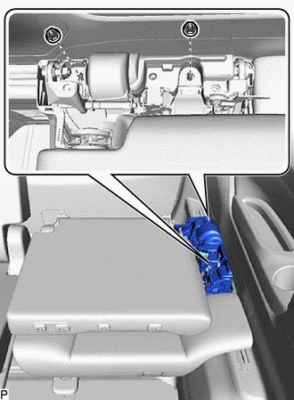
Install stopper bolt <B> and stopper bolt <A>, in that order, as shown in the illustration.
- Torque:
- 21 N*m { 214 kgf*cm, 15 ft.*lbf }
Note
For the stopper bolts, use replacement parts (72702-58120 and 72702-58110) or bolts which conform to the appropriate measurements (M8 x 1.25)
Tech Tips
The dimensions of each part of the stopper bolt are shown in the following chart.
Part Dimension A 14 mm B 15.5 mm or more C 10 mm or less D 72702-58110 Bolt <A> 45.7 mm 72702-58120 Bolt <B> 66.2 mm E 72702-58110 Bolt <A> 27.7 mm 72702-58120 Bolt <B> 48.2 mm F 18 mm G 2.5 mm or less H 1.0 mm or less I 0.75 mm or less J 5.5 mm 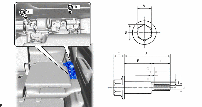
*a Bolt <A> *b Bolt <B> -
Remove the 2 nuts and disconnect the rear No. 2 seat outer belt assembly LH.
-
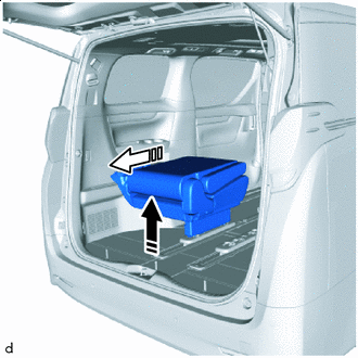
Remove in this Direction (1) 
Remove in this Direction (2) Move the rear No. 2 seat assembly LH as shown in the illustration, and then take the rear No. 2 seat assembly LH out of the vehicle through the back door.
Note
Do not damage the rear No. 2 seat assembly LH, body and body interior.
-