AIR CONDITIONING SYSTEM, Diagnostic DTC:B1461/61
| DTC Code | DTC Name |
|---|---|
| B1461/61 | Emission Gas NOx Sensor Circuit |
DESCRIPTION
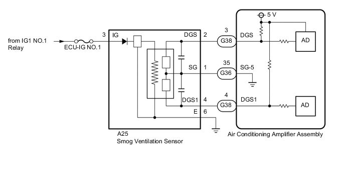
The smog ventilation sensor is installed to the front of the cooler condenser assembly to automatically control the air inlet mode (fresh, recirculation/fresh and recirculation).
This sensor detects NOx in exhaust gasses and transmits signals to the air conditioning amplifier assembly.
| DTC No. | Detection Item | DTC Detection Condition | Trouble Area | Memory | Note |
|---|---|---|---|---|---|
| B1461/61 | Emission Gas NOx Sensor Circuit | Open or short in emission gas NOx sensor circuit (w/ Mirror Heater) |
|
Memorized | - |
Tech Tips
The air conditioning amplifier assembly stores the DTC of the respective malfunction if it has occurred for the period of time indicated in the parentheses.
WIRING DIAGRAM
CAUTION / NOTICE / HINT
Note
-
Inspect the fuses for circuits related to this system before performing the following procedure.
-
If DTCs B1418/18 and B1461/61 are stored simultaneously, there may be a malfunction in the smog ventilation sensor power source related circuits.
-
When the battery is disconnected or the air conditioning amplifier assembly is replaced, be sure to perform servo motor initialization.
PROCEDURE
-
READ VALUE USING GTS (EMISSION GAS NOX SENSOR)
-
Connect the GTS to the DLC3.
-
Turn the engine switch on (IG).
-
Turn the GTS on.
-
Allow exhaust gas (NOx) to travel to the sensing portion of the smog ventilation sensor.
-
Enter the following menus: Body Electrical / Air Conditioner / Data List.
-
Read the Data List according to the display on the GTS.
Tester Display Measurement Item Range Normal Condition Diagnostic Note Emission Gas NOx Sensor Emission gas (NOx) Min.: 0
Max.: 255
Smog ventilation sensor value increases as gas amount increases Smog ventilation sensor malfunction (emission gas [NOx] detected) OK The display is as specified in the normal condition column. Result Result Proceed to OK (When troubleshooting according to the DTC) A OK (When troubleshooting according to Problem Symptoms Table) B NG C
A 
REPLACE AIR CONDITIONING AMPLIFIER ASSEMBLY for LHD: Click here for RHD: Click here
B
PROCEED TO NEXT SUSPECTED AREA SHOWN IN PROBLEM SYMPTOMS TABLE Click here
C 
-
-
CHECK HARNESS AND CONNECTOR (SMOG VENTILATION SENSOR - IG POWER SOURCE AND BODY GROUND)
-
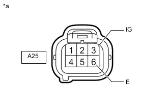
*a Front view of harness connector
(to Smog Ventilation Sensor)
Disconnect the smog ventilation sensor connector.
-
Measure the resistance according to the value(s) in the table below.
Standard Resistance Tester Connection Condition Specified Condition A25-6 (E) - Body ground Always Below 1 Ω -
Measure the voltage according to the value(s) in the table below.
Standard Voltage Tester Connection Switch Condition Specified Condition A25-3 (IG) - Body ground Engine switch on (IG) 11 to 14 V A25-3 (IG) - Body ground Engine switch off Below 1 V Result Proceed to OK NG
NG
REPAIR OR REPLACE HARNESS OR CONNECTOR
OK
-
-
INSPECT SMOG VENTILATION SENSOR
-
Remove the smog ventilation sensor.
-
Inspect the smog ventilation sensor.
Result Proceed to OK NG
NG
REPLACE SMOG VENTILATION SENSOR Click here
OK
-
-
CHECK HARNESS AND CONNECTOR (SMOG VENTILATION SENSOR - AIR CONDITIONING AMPLIFIER ASSEMBLY)
-
Disconnect the A25 smog ventilation sensor connector.
-
Disconnect the G36 and G38 air conditioning amplifier assembly connectors.
-
Measure the resistance according to the value(s) in the table below.
Standard Resistance Tester Connection Condition Specified Condition A25-1 (SG) - G36-35 (SG-5) Always Below 1 Ω A25-4 (DGS1) - G38-4 (DGS) Always Below 1 Ω A25-1 (SG) or G36-35 (SG-5) - Body ground Always 10 kΩ or higher A25-4 (DGS1) or G38-4 (DGS) - Body ground Always 10 kΩ or higher Result Proceed to OK NG
OK
REPLACE AIR CONDITIONING AMPLIFIER ASSEMBLY for LHD: Click here for RHD: Click here
NG
REPAIR OR REPLACE HARNESS OR CONNECTOR
-