AIR CONDITIONING SYSTEM, Diagnostic DTC:B1497/97
| DTC Code | DTC Name |
|---|---|
| B1497/97 | BUS IC Communication Malfunction |
DESCRIPTION
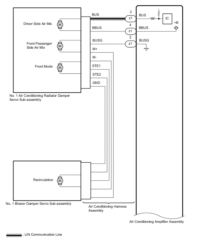
The air conditioning harness assembly connects the air conditioning amplifier assembly and the servo motors. The air conditioning amplifier assembly supplies power and sends operation instructions to each servo motor through the air conditioning harness assembly. Each servo motor sends damper position information to the air conditioning amplifier assembly.
| DTC No. | Detection Item | DTC Detection Condition | Trouble Area | Memory | Note |
|---|---|---|---|---|---|
| B1497/97 | BUS IC Communication Malfunction | Error or open in communication line |
|
Memorized (10 seconds or more) | - |
Tech Tips
The air conditioning amplifier assembly stores the DTC of the respective malfunction if it has occurred for the period of time indicated in the parentheses.
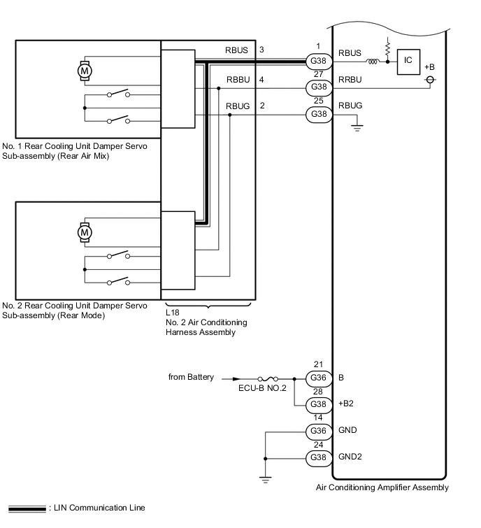
WIRING DIAGRAM
CAUTION / NOTICE / HINT
Note
-
Inspect the fuses for circuits related to this system before performing the following procedure.
-
When the battery is disconnected or the air conditioning amplifier assembly is replaced, be sure to perform servo motor initialization.
PROCEDURE
-
CHECK FOR DTC
-
Clear the DTC.
Body Electrical > Air Conditioner > Clear DTCs -
Check for DTCs.
Body Electrical > Air Conditioner > Trouble CodesOK DTC B1497/97 is not output. Result Proceed to OK NG
OK 
USE SIMULATION METHOD TO CHECK Click here
NG 
-
-
CHECK HARNESS AND CONNECTOR (AIR CONDITIONING AMPLIFIER ASSEMBLY - BATTERY AND BODY GROUND)
-
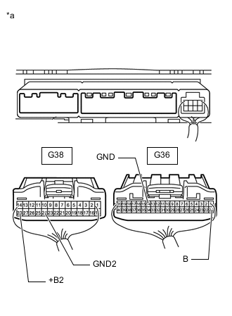
*a Rear view of wire harness connector
(to Air Conditioning Amplifier Assembly)
Disconnect the air conditioning amplifier assembly connectors.
-
Measure the resistance according to the value(s) in the table below.
Standard Resistance Tester Connection Condition Specified Condition G36-14 (GND) - Body ground Always Below 1 Ω G38-24 (GND2) - Body ground Always Below 1 Ω -
Measure the voltage according to the value(s) in the table below.
Standard Voltage Tester Connection Condition Specified Condition G36-21 (B) - Body ground Always 11 to 14 V G38-28 (+B2) - Body ground Always 11 to 14 V Result Proceed to OK NG
NG
REPAIR OR REPLACE HARNESS OR CONNECTOR
OK
-
-
PERFORM ACTIVE TEST USING GTS
-
Connect the GTS to the DLC3.
-
Turn the engine switch on (IG).
-
Turn the GTS on.
-
Enter the following menus: Body Electrical / Air Conditioner / Active Test.
-
Check the operation by referring to the table below.
Body Electrical > Air Conditioner > Active TestTester Display Measurement Item Control Range Diagnostic Note Air Mix Servo Targ Pulse(D) No. 1 air conditioning radiator damper servo sub-assembly (driver side air mix) target pulse Min.: 128
Max.: 383
-
Operates between 165 and 257 pulse
for LHD:
-
Operates between 255 and 347 pulses
for RHD:
Air Mix Servo Targ Pulse(P) No. 1 air conditioning radiator damper servo sub-assembly (front passenger side air mix) target pulse Min.: 128
Max.: 383
-
Operates between 255 and 347 pulse
for LHD:
-
Operates between 165 and 257 pulse
for RHD:
Air Outlet Servo Pulse (D) No. 1 air conditioning radiator damper servo sub-assembly (front mode) target pulse Min.: 128
Max.: 383
Operates between 234 and 348 pulses Air Inlet Damper Targ Pulse No. 1 blower damper servo sub-assembly (recirculation) target pulse Min.: 128
Max.: 383
Operates between 235 and 258 pulses Rear Air Mix Servo Targ Pulse No. 1 rear cooling unit damper servo motor sub-assembly (rear air mix) target pulse Min.: 128
Max.: 383
Operates between 254 and 299 pulses A/O Servo Pulse(Rr D) No. 2 rear cooling unit damper servo motor sub-assembly (rear mode) pulse Min.: 128
Max.: 383
Operates between 200 and 276 pulses
Body Electrical > Air Conditioner > Active TestTester Display Air Mix Servo Targ Pulse(D)
Body Electrical > Air Conditioner > Active TestTester Display Air Mix Servo Targ Pulse(P)
Body Electrical > Air Conditioner > Active TestTester Display Air Outlet Servo Pulse (D)
Body Electrical > Air Conditioner > Active TestTester Display Air Inlet Damper Targ Pulse
Body Electrical > Air Conditioner > Active TestTester Display Rear Air Mix Servo Targ Pulse
Body Electrical > Air Conditioner > Active TestTester Display A/O Servo Pulse(Rr D) OK Arm of the damper servo motor selected in the Active Test moves smoothly. -
-
According to the test result, proceed to the next step.
Result Result Proceed to No. 1 air conditioning radiator damper servo sub-assembly is malfunctioning A No. 1 blower damper servo sub-assembly is malfunctioning B All front damper servo motors are malfunctioning C No. 1 rear cooling unit damper servo sub-assembly is malfunctioning D No. 2 rear cooling unit damper servo sub-assembly is malfunctioning E All rear damper servo motors are malfunctioning F
B 
CHECK NO. 1 BLOWER DAMPER SERVO SUB-ASSEMBLY Click here
C
CHECK AIR CONDITIONING HARNESS ASSEMBLY Click here
D
CHECK NO. 1 REAR COOLING UNIT DAMPER SERVO SUB-ASSEMBLY Click here
E
CHECK NO. 2 REAR COOLING UNIT DAMPER SERVO SUB-ASSEMBLY Click here
F
CHECK HARNESS AND CONNECTOR (AIR CONDITIONING AMPLIFIER ASSEMBLY - NO. 2 AIR CONDITIONING HARNESS ASSEMBLY) Click here
A
-
-
CHECK NO. 1 AIR CONDITIONING RADIATOR DAMPER SERVO SUB-ASSEMBLY
-
Replace the No. 1 air conditioning radiator damper servo sub-assembly.
-
for LHD: Click here
-
for RHD: Click here
Tech Tips
Since the servo motor cannot be inspected while it is removed from the vehicle, replace the servo motor with a new or known good one and check that the condition returns to normal.
-
-
Clear the DTC.
Body Electrical > Air Conditioner > Clear DTCs -
Check for DTCs.
Body Electrical > Air Conditioner > Trouble CodesOK DTC B1497/97 is not output. Result Proceed to OK NG
OK
END (NO. 1 AIR CONDITIONING RADIATOR DAMPER SERVO SUB-ASSEMBLY IS DEFECTIVE)
NG
GO TO STEP 6 Click here
-
-
CHECK NO. 1 BLOWER DAMPER SERVO SUB-ASSEMBLY
-
Replace the No. 1 blower damper servo sub-assembly.
-
for LHD: Click here
-
for RHD: Click here
Tech Tips
Since the servo motor cannot be inspected while it is removed from the vehicle, replace the servo motor with a new or known good one and check that the condition returns to normal.
-
-
Clear the DTC.
Body Electrical > Air Conditioner > Clear DTCs -
Check for DTCs.
Body Electrical > Air Conditioner > Trouble CodesOK DTC B1497/97 is not output. Result Proceed to OK NG
OK
END (NO. 1 BLOWER DAMPER SERVO SUB-ASSEMBLY IS DEFECTIVE)
NG
-
-
CHECK AIR CONDITIONING HARNESS ASSEMBLY
-
Replace the air conditioning harness assembly.
-
for LHD: Click here
-
for RHD: Click here
Tech Tips
Since the air conditioning harness assembly cannot be inspected while it is removed from the vehicle, replace the air conditioning harness assembly with a new or known good one and check that the condition returns to normal.
-
-
Clear the DTC.
Body Electrical > Air Conditioner > Clear DTCs -
Check for DTCs.
Body Electrical > Air Conditioner > Trouble CodesOK DTC B1497/97 is not output. Result Proceed to OK NG
OK
END (AIR CONDITIONING HARNESS ASSEMBLY IS DEFECTIVE)
NG
REPLACE AIR CONDITIONING HARNESS ASSEMBLY for LHD: Click here for RHD: Click here
-
-
CHECK NO. 1 REAR COOLING UNIT DAMPER SERVO SUB-ASSEMBLY
-
Replace the No. 1 rear cooling unit damper servo sub-assembly.
-
Clear the DTC.
Body Electrical > Air Conditioner > Clear DTCs -
Check for DTCs.
Body Electrical > Air Conditioner > Trouble CodesOK DTC B1497/97 is not output. Result Proceed to OK NG
OK
END (NO. 1 REAR COOLING UNIT DAMPER SERVO SUB-ASSEMBLY IS DEFECTIVE)
NG
GO TO STEP 9 Click here
-
-
CHECK NO. 2 REAR COOLING UNIT DAMPER SERVO SUB-ASSEMBLY
-
Replace the No. 2 rear cooling unit damper servo sub-assembly.
-
Clear the DTC.
Body Electrical > Air Conditioner > Clear DTCs -
Check for DTCs.
Body Electrical > Air Conditioner > Trouble CodesOK DTC B1497/97 is not output. Result Proceed to OK NG
OK
END (NO. 2 REAR COOLING UNIT DAMPER SERVO SUB-ASSEMBLY IS DEFECTIVE)
NG
-
-
CHECK HARNESS AND CONNECTOR (AIR CONDITIONING AMPLIFIER ASSEMBLY - NO. 2 AIR CONDITIONING HARNESS ASSEMBLY)
-
Disconnect the G38 air conditioning amplifier assembly connector.
-
Disconnect the L18 No. 2 air conditioning harness assembly connector.
-
Measure the resistance according to the value(s) in the table below.
Standard Resistance Tester Connection Condition Specified Condition G38-1 (RBUS) - L18-3 (RBUS) Always Below 1 Ω G38-27 (RBBU) - L18-4 (RBBU) Always Below 1 Ω G38-25 (RBUG) - L18-2 (RBUG) Always Below 1 Ω G38-1 (RBUS) or L18-3 (RBUS) - Body ground Always 10 kΩ or higher G38-27 (RBBU) or L18-4 (RBBU) - Body ground Always 10 kΩ or higher G38-25 (RBUG) or L18-2 (RBUG) - Body ground Always 10 kΩ or higher Result Proceed to OK NG
NG
REPAIR OR REPLACE HARNESS OR CONNECTOR
OK
-
-
CHECK NO. 2 AIR CONDITIONING HARNESS ASSEMBLY
-
Replace the No. 2 air conditioning harness assembly.
-
Clear the DTC.
Body Electrical > Air Conditioner > Clear DTCs -
Check for DTCs.
Body Electrical > Air Conditioner > Trouble CodesOK DTC B1497/97 is not output. Result Proceed to OK NG
OK
END (NO. 2 AIR CONDITIONING HARNESS ASSEMBLY IS DEFECTIVE)
NG
REPLACE AIR CONDITIONING AMPLIFIER ASSEMBLY for LHD: Click here for RHD: Click here
-