AIR CONDITIONING SYSTEM, Diagnostic DTC:B14B9
| DTC Code | DTC Name |
|---|---|
| B14B9 | Open in Ion Generator Circuit |
DESCRIPTION
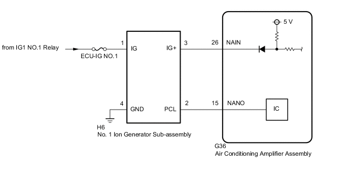
The No. 1 ion generator sub-assembly operates when the blower switch is on. The air conditioning amplifier assembly sends a drive signal to the No. 1 ion generator sub-assembly. When the No. 1 ion generator sub-assembly receives the drive signal and starts to operate, it outputs an operation condition signal to the air conditioning amplifier assembly.
| DTC No. | Detection Item | DTC Detection Condition | Trouble Area | Memory | Note |
|---|---|---|---|---|---|
| B14B9 | Open in Ion Generator Circuit | Open in No. 1 ion generator sub-assembly circuit |
|
Memorized (12 seconds or more) |
- |
Tech Tips
The air conditioning amplifier assembly stores the DTC of the respective malfunction if it has occurred for the period of time indicated in the parentheses.
WIRING DIAGRAM
CAUTION / NOTICE / HINT
Note
-
Inspect the fuses for circuits related to this system before performing the following procedure.
-
When the battery is disconnected or the air conditioning amplifier assembly is replaced, be sure to perform servo motor initialization.
PROCEDURE
-
PERFORM ACTIVE TEST USING GTS (ION GENERATOR)
-
Connect the GTS to the DLC3.
-
Turn the engine switch on (IG).
-
Turn the GTS on.
-
Enter the following menus: Body Electrical / Air Conditioner / Active Test.
-
Check the operation by referring to the table below.
Body Electrical > Air Conditioner > Active TestTester Display Measurement Item Control Range Diagnostic Note Ion Generator Ion generator OFF/ON -
Body Electrical > Air Conditioner > Active TestTester Display Ion Generator OK Ion generator changes using GTS. Result Proceed to OK NG
OK 
REPLACE AIR CONDITIONING AMPLIFIER ASSEMBLY for LHD: Click here for RHD: Click here
NG 
-
-
CHECK HARNESS AND CONNECTOR (NO. 1 ION GENERATOR SUB-ASSEMBLY - POWER SOURCE AND BODY GROUND)
-
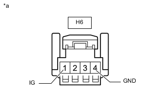
*a Front view of air conditioning harness assembly
(to No. 1 Ion Generator Sub-assembly)
Disconnect the No. 1 ion generator sub-assembly connector.
-
Measure the resistance according to the value(s) in the table below.
Standard Resistance Tester Connection Condition Specified Condition H6-4 (GND) - Body ground Always Below 1 Ω -
Measure the voltage according to the value(s) in the table below.
Standard Voltage Tester Connection Switch Condition Specified Condition H6-1 (IG) - Body ground Engine switch off Below 1 V H6-1 (IG) - Body ground Engine switch on (IG) 11 to 14 V Result Proceed to OK NG
NG
REPAIR OR REPLACE HARNESS OR CONNECTOR
OK
-
-
CHECK HARNESS AND CONNECTOR (NO. 1 ION GENERATOR SUB-ASSEMBLY - AIR CONDITIONING AMPLIFIER ASSEMBLY)
-
Disconnect the H6 No. 1 ion generator sub-assembly connector.
-
Disconnect the G36 air conditioning amplifier assembly connector.
-
Measure the resistance according to the value(s) in the table below.
Standard Resistance Tester Connection Condition Specified Condition G36-26 (NAIN) - H6-3 (IG+) Always Below 1 Ω G36-15 (NANO) - H6-2 (PCL) Always Below 1 Ω G36-26 (NAIN) or H6-3 (IG+) - Body ground Always 10 kΩ or higher G36-15 (NANO) or H6-2 (PCL) - Body ground Always 10 kΩ or higher H6-3 (IG+) - H6-2 (PCL) Always 10 kΩ or higher Result Proceed to OK NG
NG
REPAIR OR REPLACE HARNESS OR CONNECTOR
OK
-
-
REPLACE NO.1 ION GENERATOR SUB-ASSEMBLY
-
Replace the No. 1 ion generator sub-assembly.
Tech Tips
Since the No. 1 ion generator sub-assembly cannot be inspected while it is removed from the vehicle, replace the No. 1 ion generator sub-assembly with a new or known good one and check that the condition ion returns to normal.
-
Check for DTCs.
Body Electrical > Air Conditioner > Trouble CodesOK DTC B14B9 is not output. Result Proceed to OK NG
OK
END (NO. 1 ION GENERATOR SUB-ASSEMBLY IS DEFECTIVE)
NG
REPLACE AIR CONDITIONING AMPLIFIER ASSEMBLY for LHD: Click here for RHD: Click here
-