FRONT AIR CONDITIONING UNIT(for RHD) INSTALLATION
CAUTION / NOTICE / HINT
PROCEDURE
-
INSTALL AIR CONDITIONER UNIT ASSEMBLY
-
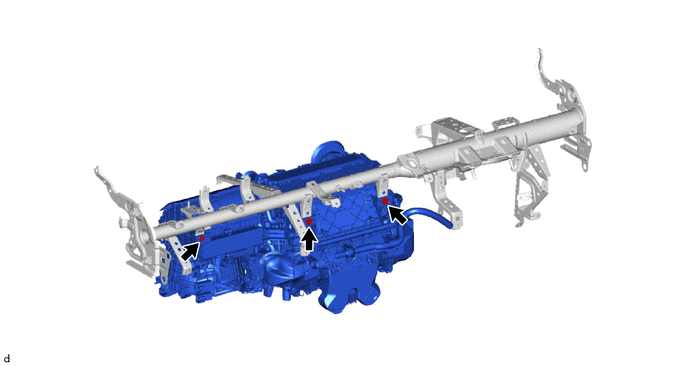
Temporarily install the air conditioner unit assembly to the instrument panel reinforcement assembly with the 3 bolts.
-
-
INSTALL INSTRUMENT PANEL REINFORCEMENT ASSEMBLY WITH AIR CONDITIONER UNIT ASSEMBLY
Note
-
Be sure to support the air conditioner unit assembly when installing it because failure to do so may cause the bracket of the air conditioner unit assembly to break.
-
When installing the air conditioner unit, eliminate static electricity by touching the vehicle body to prevent the components from being damaged.
-
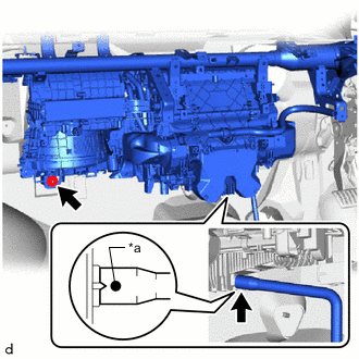
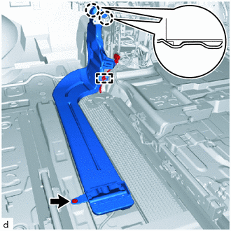
*a Standard Position Temporarily install the instrument panel reinforcement assembly with air conditioner unit assembly.
-
Align the standard position, install the drain cooler hose.
-
Tighten the nut.
-
Using an 8 mm hexagon wrench, tighten the 2 movable collars.
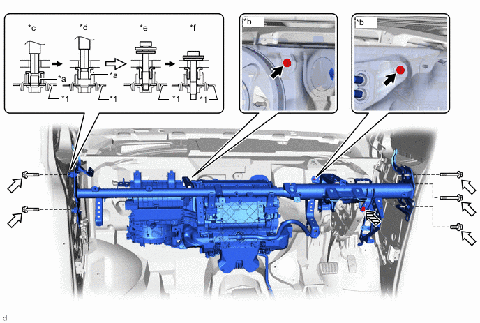
*1 Instrument Panel Reinforcement Assembly - - *a Movable Collar *b Vehicle Body *c Step 1 *d Step 2 *e Step 3 *f Step 4 
Bolt A 
Bolt B 
Bolt C - - -
Install the instrument panel reinforcement assembly with the 8 bolts.
- Torque:
- Bolt A
- 12.5 N*m { 127 kgf*cm, 9 ft.*lbf }
- Bolt B
- 18 N*m { 184 kgf*cm, 13 ft.*lbf }
- Bolt C
- 23.6 N*m { 241 kgf*cm, 17 ft.*lbf }
-
-
INSTALL DEFROSTER NOZZLE ASSEMBLY
-
Attach the claw to install the defroster nozzle assembly.
-
Attach the clamp.
-
-
INSTALL INSTRUMENT PANEL SAFETY PAD CAP
-
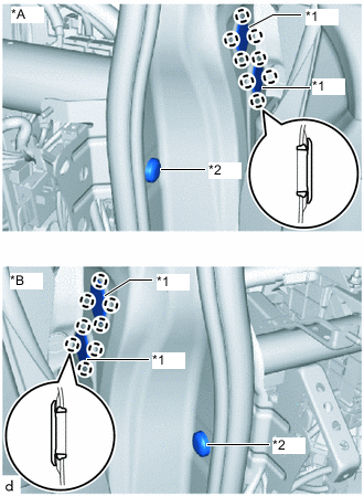
*A for Driver Side *B for Passenger Side *1 Instrument Panel Hole Plug *2 Instrument Panel Safety Pad Cap Install 2 new instrument panel safety pad caps.
-
Attach the claw to install the 4 new instrument panel hole plugs.
-
-
INSTALL NO. 1 INSTRUMENT PANEL BRACE SUB-ASSEMBLY
-
Nut Screw Install the No. 1 instrument panel brace sub-assembly with the 2 screws.
-
Install the 2 nuts.
-
-
INSTALL NO. 2 INSTRUMENT PANEL TO FLOOR BRACE SUB-ASSEMBLY
-
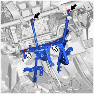
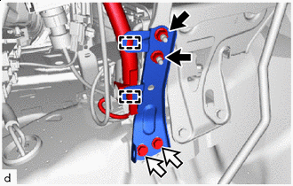
Nut Bolt Install the No. 2 instrument panel to floor brace sub-assembly with the 2 nuts and bolt.
-
Attach the clamp.
-
-
INSTALL NO. 1 INSTRUMENT PANEL TO FLOOR BRACE SUB-ASSEMBLY
-
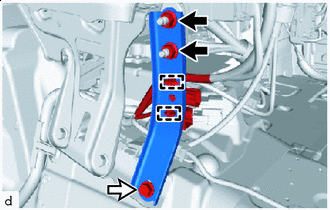
Nut Bolt Install the No. 1 instrument panel to floor brace sub-assembly with the 2 nuts and 2 bolts.
-
Attach the clamp.
-
-
INSTALL AIR CONDITIONER UNIT ASSEMBLY
-
Bolt Screw Tighten the 2 screws and 3 bolts in the order shown in the illustration.
-
-
INSTALL INSTRUMENT PANEL WIRE
-
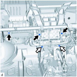
Install each bolt, nut and screw, and then connect the instrument panel wire.
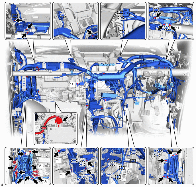
*A w/ PTC Heater - - *1 Ground Wire - - -
Connect each connector and attach each clamp.
-
Install each bolt and each ground wire.
- Torque:
- 8.3 N*m { 85 kgf*cm, 73 in.*lbf }
-
-
INSTALL REAR NO. 1 AIR DUCT
-
Attach the claw to install the rear No. 1 air duct.
-
-
INSTALL REAR NO. 3 AIR DUCT
-
except Super Long Slide Seat:
-
Attach the claw to install the rear No. 3 air duct.
-
-
for Super Long Slide Seat:
-
Attach the claw to install the rear No. 3 air duct.
-
Attach the clamp.
-
Install the clip.
-
-
-
INSTALL REAR NO. 5 AIR DUCT
-
Attach the claw to install the rear No. 5 air duct.
-
Install the clip.
-
-
INSTALL REAR NO. 2 AIR DUCT
-
Attach the claw to install the rear No. 2 air duct.
-
-
INSTALL REAR NO. 4 AIR DUCT
-
Attach the claw to install the rear No. 4 air duct.
-
Install the clip.
-
-
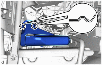
INSTALL FRONT FLOOR SIDE PAD LH
-
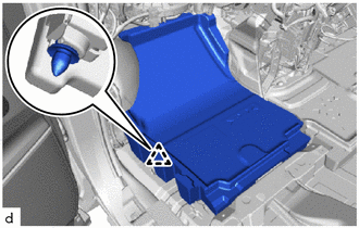
except Super Long Slide Seat:
-
Attach the clip to install the front floor side pad LH.
-
-
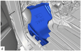
for Super Long Slide Seat:
-
Install the front floor side pad LH.
-
-
-
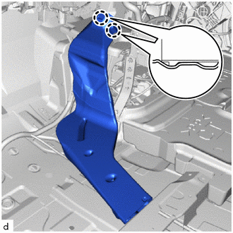
INSTALL FRONT FLOOR SIDE PAD RH
-
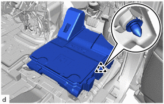
Attach the clip to install the front floor side pad RH.
-
-
INSTALL FRONT FLOOR CARPET ASSEMBLY
-
for Integrated Console Box Type:
-
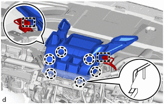
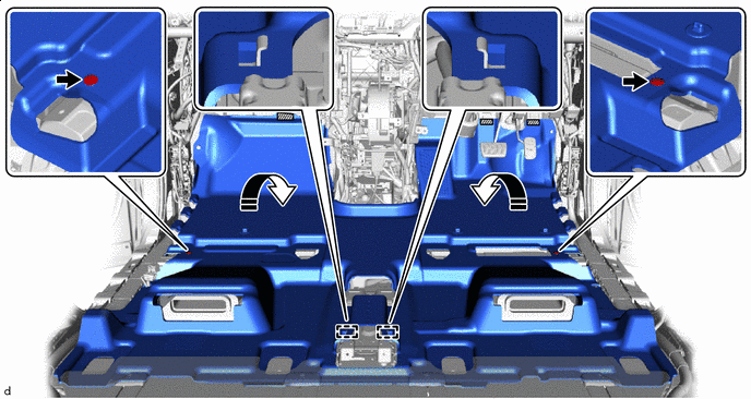
Attach the guide to install the front floor carpet assembly to the original position as shown in the illustration.
-
Attach each fastener.
-
Install the clip.
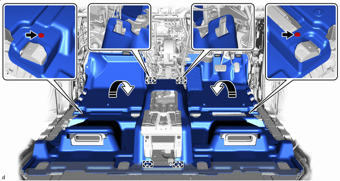

Fastener 
Install in this Direction
-
-
for Separate Console Box Type:
-
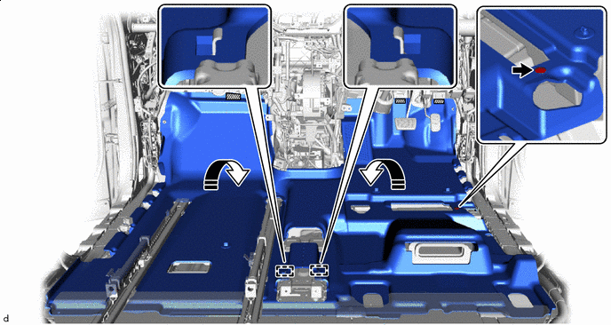
Attach the guide to install the front floor carpet assembly to the original position as shown in the illustration.
-
Attach each fastener.
-
Install the clip.
Fastener Install in this Direction
-
-
for Super Long Slide Seat:
-
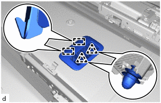
Attach the guide to install the front floor carpet assembly to the original position as shown in the illustration.
-
Attach each fastener.
-
Install the clip.
Fastener Install in this Direction
-
-
-
INSTALL LOWER CENTER PILLAR GARNISH LH
-
INSTALL LOWER CENTER PILLAR GARNISH RH
-
INSTALL LAP BELT OUTER ANCHOR COVER
-
INSTALL NO. 2 ASSIST GRIP
-
INSTALL NO. 1 ASSIST GRIP
-
INSTALL ASSIST GRIP PLUG
-
INSTALL ASSIST GRIP PLUG
-
INSTALL REAR DOOR SCUFF PLATE LH
-
INSTALL REAR DOOR SCUFF PLATE RH
-
INSTALL NO. 3 SEAT TRACK LOWER RAIL PROTECTOR (for Super Long Slide Seat)
-
INSTALL NO. 2 SEAT TRACK LOWER RAIL PROTECTOR (for Super Long Slide Seat)
-
INSTALL NO. 1 SEAT TRACK LOWER RAIL PROTECTOR (for Super Long Slide Seat)
-
INSTALL REAR SEAT LOCK STRIKER COVER (for Super Long Slide Seat)
-
INSTALL NO. 3 FLOOR CARPET MOULDING (for Super Long Slide Seat)
-
INSTALL HEATER AIR OUTLET GRILLE (for Super Long Slide Seat)
-
Install 2 new clips to the heater air outlet grille.
-
Attach the claw and clip to install the heater air outlet grille.
-
-
INSTALL COWL SIDE TRIM BOARD LH (for Super Long Slide Seat)
-
INSTALL DOOR SCUFF PLATE ASSEMBLY LH (for Super Long Slide Seat)
-
INSTALL NO. 1 AIR DUCT SUB-ASSEMBLY
-
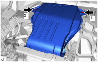
Temporarily install the No. 1 air duct sub-assembly.
-
Tighten the 2 nuts in the order shown in the illustration.
-
-
INSTALL SHIFT LEVER ASSEMBLY
-
for 2AR-FE:
-
for 2GR-FE:
-
-
INSTALL STEERING COLUMN ASSEMBLY
-
INSTALL NO. 4 AIR DUCT SUB-ASSEMBLY
-
Attach the claw to install the No. 4 air duct sub-assembly.
-
Install the clip.
-
-
INSTALL CONSOLE BOX ASSEMBLY (for Separate Console Box Type)
-
INSTALL INSTRUMENT PANEL SAFETY PAD ASSEMBLY
-
INSTALL REAR NO. 2 SEAT ASSEMBLY LH (for Super Long Slide Seat)
-
INSTALL REAR NO. 1 SEAT ASSEMBLY LH (for Super Long Slide Seat)
-
INSTALL FRONT SEAT ASSEMBLY LH
-
for Manual Seat:
-
for Driver Side Power Seat:
-
for Front Passenger Side Power Seat:
-
for Super Long Slide Seat:
-
-
INSTALL FRONT SEAT ASSEMBLY RH
Tech Tips
Use the same procedure described for the LH side.
-
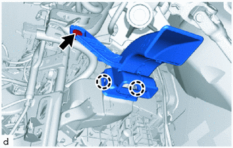
CONNECT HEATER GROMMET
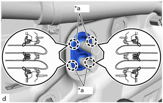
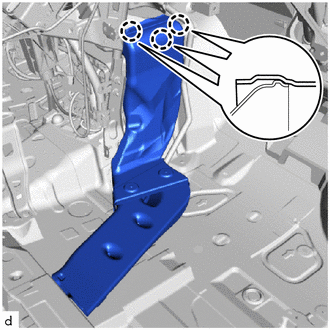
*a Marked Part
-
Press the marked parts to attach the claw and install the heater grommet.
Note
-
Securely install the heater grommet in order to prevent water ingress.
-
Install the heater grommet so that there is no clearance between the grommet and heater pipe.
-
-
-
CONNECT HEATER WATER HOSE OUTLET
-
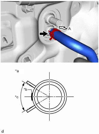
*a View A *b for 2AR-FE: Marking (White)
for 2GR-FE: Marking (Green)
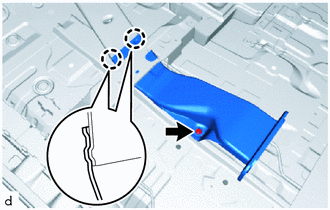
*c Clip Installation Angle (90°) Connect the heater water hose outlet with the marking facing left and attach the clip within the area shown in the illustration.
Note
Do not apply excessive force to the heater water hose outlet.
-
-
CONNECT HEATER WATER HOSE INLET
-
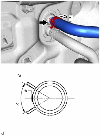
*a View A *b for 2AR-FE: Marking (White)
for 2GR-FE: Marking (Green)
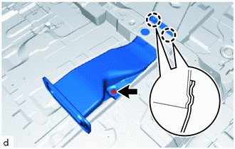
*c Clip Installation Angle (90°) Connect the heater water hose inlet with the marking facing left and attach the clip within the area shown in the illustration.
Note
Do not apply excessive force to the heater water hose inlet.
-
-
CONNECT NO. 2 AIR CONDITIONER TUBE AND ACCESSORY ASSEMBLY
-
Remove the vinyl tape from the No. 2 air conditioner tube and accessory assembly.
-
Sufficiently apply compressor oil to a new O-ring and the fitting surface of the No. 2 air conditioner tube and accessory assembly.
Compressor Oil ND-OIL 8 or equivalent -
Install the O-ring to the No. 2 air conditioner tube and accessory assembly.
Note
Keep the O-rings and O-ring fitting surfaces free of foreign matter.
-
Connect the No. 2 air conditioner tube and accessory assembly.
-
-
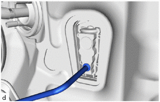
CONNECT AIR CONDITIONER TUBE AND ACCESSORY ASSEMBLY
-
Remove the vinyl tape from the air conditioner tube and accessory assembly.
-
Sufficiently apply compressor oil to a new O-ring and the fitting surface of the air conditioner tube and accessory assembly.
Compressor Oil ND-OIL 8 or equivalent -
Install the O-ring to the air conditioner tube and accessory assembly.
Note
Keep the O-rings and O-ring fitting surfaces free of foreign matter.
-
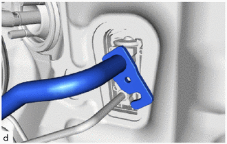
Connect the air conditioner tube and accessory assembly.
-
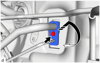
Install in this Direction Rotate the hook connector as shown in the illustration.
-
Insert the pipe joint into the fitting hole securely and tighten the bolt.
- Torque:
- 5.4 N*m { 55 kgf*cm, 48 in.*lbf }
-
-
INSTALL OUTER COWL TOP PANEL SUB-ASSEMBLY
-
INSTALL NO. 2 HEATER AIR DUCT SPLASH SHIELD SEAL
-
INSTALL NO. 1 HEATER AIR DUCT SPLASH SHIELD SEAL
-
INSTALL BRAKE MASTER CYLINDER RESERVOIR ASSEMBLY
-
INSTALL WINDSHIELD WIPER MOTOR AND LINK
-
INSPECT WASHER NOZZLE
-
ADD ENGINE COOLANT
-
for 2AR-FE:
-
for 2GR-FE:
-
-
INSPECT FOR COOLANT LEAK
-
for 2AR-FE:
-
for 2GR-FE:
-
-
CHARGE AIR CONDITIONING SYSTEM WITH REFRIGERANT
-
WARM UP ENGINE
-
INSPECT FOR REFRIGERANT LEAK
-
INITIALIZATION SERVO MOTOR