FRONT AIR CONDITIONING UNIT(for RHD) REMOVAL
CAUTION / NOTICE / HINT
The necessary procedures (adjustment, calibration, initialization or registration) that must be performed after parts are removed, installed or replaced during the front air conditioning unit (for RHD) removal/installation are shown below.
| Replacement Part or Procedure | Necessary Procedures | Effects / Inoperative when not Performed | Link |
|---|---|---|---|
| Disconnect cable from negative battery terminal | Drive the vehicle until stop and start control is permitted (approximately 5 to 60 minutes) | Stop and start system (for 2AR-FE) | |
| Stop and start system (for 2GR-FKS) | |||
| Memorize steering angle neutral point | Panoramic view monitor system | ||
| Initialize back door lock | Power door lock control system | ||
| Initialize servo motor | Air conditioning system | ||
| Reset slide door close position | Power slide door system | ||
| Reset back door close position | Power back door system |
CAUTION:
Some of these service operations affect the SRS airbag system. Read the precautionary notices concerning the SRS airbag system before servicing.
PROCEDURE
-
RECOVER REFRIGERANT FROM REFRIGERATION SYSTEM
-
DRAIN ENGINE COOLANT
-
for 2AR-FE:
-
for 2GR-FKS:
-
-
REMOVE WINDSHIELD WIPER MOTOR AND LINK
-
DISCONNECT BRAKE MASTER CYLINDER RESERVOIR ASSEMBLY
-
REMOVE NO. 2 HEATER AIR DUCT SPLASH SHIELD SEAL
-
REMOVE NO. 1 HEATER AIR DUCT SPLASH SHIELD SEAL
-
REMOVE OUTER COWL TOP PANEL SUB-ASSEMBLY
-
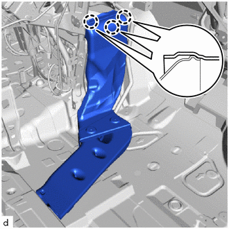
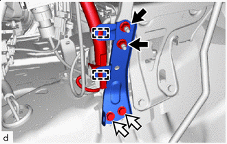
DISCONNECT AIR CONDITIONER TUBE AND ACCESSORY ASSEMBLY
-
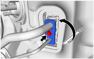

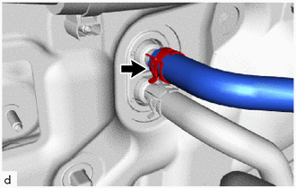
Remove in this Direction Remove the bolt and rotate the hook connector as shown in the illustration.
-
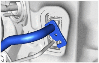
Disconnect the air conditioner tube and accessory assembly.
-
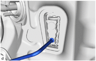
Remove the 2 O-rings from the air conditioner tube and accessory assembly.
Note
Seal the openings of the disconnected parts using vinyl tape to prevent the entry of moisture and foreign matter.
-
-
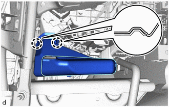
DISCONNECT NO. 2 AIR CONDITIONER TUBE AND ACCESSORY ASSEMBLY
-
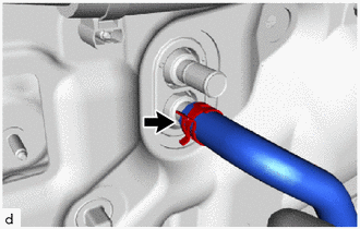
Disconnect the No. 2 air conditioner tube and accessory assembly.
-
Remove the O-ring from the No. 2 air conditioner tube and accessory assembly.
Note
Seal the openings of the disconnected parts using vinyl tape to prevent the entry of moisture and foreign matter.
-
-
DISCONNECT HEATER WATER HOSE INLET
-
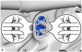
Using pliers, grip the claws of the clip and slide the clip to disconnect the heater water hose inlet.
Note
-
Do not apply excessive force to the water hose and heater water hose inlet.
-
Prepare a drain pan or cloth in case the coolant leaks.
-
-
-
DISCONNECT HEATER WATER HOSE OUTLET
-
Using pliers, grip the claws of the clip and slide the clip to disconnect the heater water hose outlet.
Note
-
Do not apply excessive force to the water hose and heater water hose outlet.
-
Prepare a drain pan or cloth in case the coolant leaks.
-
-
-
REMOVE HEATER GROMMET
-
Detach the claw and remove the heater grommet.
-
-
REMOVE FRONT SEAT ASSEMBLY LH
-
for Manual Seat:
-
for Driver Side Power Seat:
-
for Front Passenger Side Power Seat:
-
-
REMOVE FRONT SEAT ASSEMBLY RH
Tech Tips
Use the same procedure described for the LH side.
-
REMOVE INSTRUMENT PANEL SAFETY PAD ASSEMBLY
-
REMOVE CONSOLE BOX ASSEMBLY (for Separate Console Box Type)
-
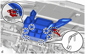
REMOVE NO. 4 AIR DUCT SUB-ASSEMBLY
-
Remove the clip.
-
Detach the claw and remove the No. 4 air duct sub-assembly.
-
-
REMOVE STEERING COLUMN ASSEMBLY
-
REMOVE SHIFT LEVER ASSEMBLY
-
for 2AR-FE:
-
for 2GR-FKS:
-
-
REMOVE NO. 1 AIR DUCT SUB-ASSEMBLY
-
Remove the 2 nuts and No. 1 air duct sub-assembly.
-
-
REMOVE REAR DOOR SCUFF PLATE LH
-
REMOVE REAR DOOR SCUFF PLATE RH
-
REMOVE ASSIST GRIP PLUG
-
REMOVE ASSIST GRIP PLUG
-
REMOVE NO. 2 ASSIST GRIP
-
REMOVE NO. 1 ASSIST GRIP
-
REMOVE LAP BELT OUTER ANCHOR COVER
-
REMOVE LOWER CENTER PILLAR GARNISH LH
-
REMOVE LOWER CENTER PILLAR GARNISH RH
-
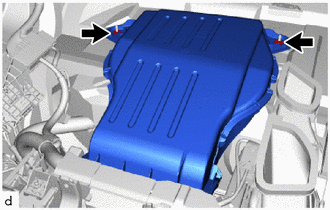
REMOVE FRONT FLOOR CARPET ASSEMBLY
-
for Integrated Console Box Type:
-
Remove the clip.
-
Detach each fastener.
-
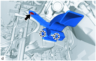
Detach the guide and fold back the front floor carpet assembly as shown in the illustration.
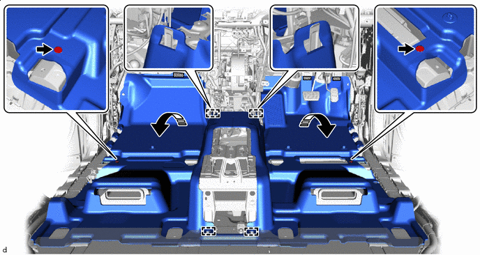

Fastener Remove in this Direction
-
-
for Separate Console Box Type:
-
Remove the clip.
-
Detach each fastener.
-
Detach the guide and fold back the front floor carpet assembly as shown in the illustration.
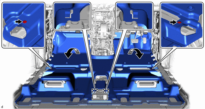
Fastener Remove in this Direction
-
-
-
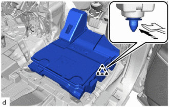
REMOVE FRONT FLOOR SIDE PAD LH
-
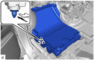
Using a clip remover, detach the clip and remove the front floor side pad LH.
-
-
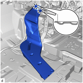
REMOVE FRONT FLOOR SIDE PAD RH
-
Using a clip remover, detach the clip and remove the front floor side pad RH.
-
-
REMOVE REAR NO. 5 AIR DUCT
-
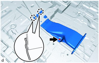
Remove the clip.
-
Detach the claw and remove the rear No. 5 air duct.
-
-
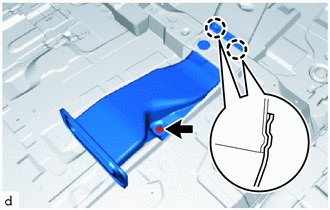
REMOVE REAR NO. 3 AIR DUCT
-
Detach the claw and remove the rear No. 3 air duct.
-
-
REMOVE REAR NO. 4 AIR DUCT
-
Remove the clip.
-
Detach the claw and remove the rear No. 4 air duct.
-
-
REMOVE REAR NO. 2 AIR DUCT
-
Detach the claw and remove the rear No. 2 air duct.
-
-
REMOVE REAR NO. 1 AIR DUCT
-
Detach the claw and remove the rear No. 1 air duct.
-
-
DISCONNECT INSTRUMENT PANEL WIRE
-
Remove each bolt and each ground wire.
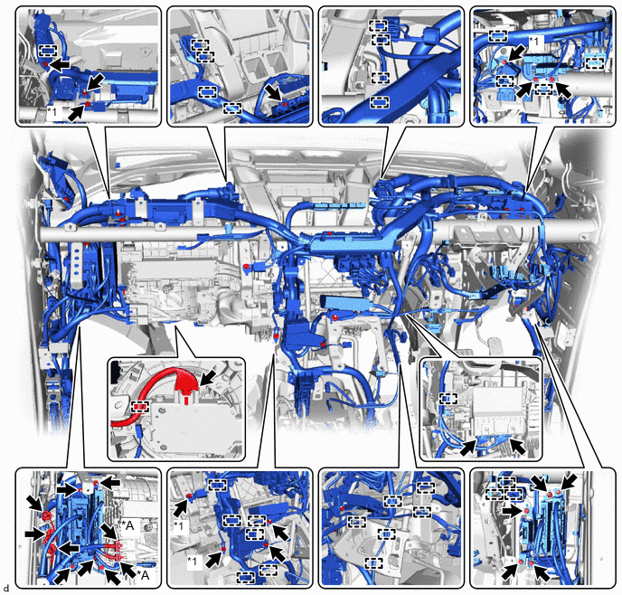
*A w/ PTC Heater - - *1 Ground Wire - - -
Disconnect each connector and detach each clamp.
-
Remove each bolt, nut and screw, and then disconnect the instrument panel wire.
-
-
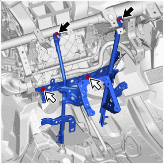
REMOVE NO. 2 INSTRUMENT PANEL TO FLOOR BRACE SUB-ASSEMBLY
-

Nut 
Bolt Detach the clamp.
-
Remove the 2 nuts, bolt and No. 2 instrument panel to floor brace sub-assembly.
-
-
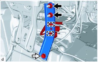
REMOVE NO. 1 INSTRUMENT PANEL TO FLOOR BRACE SUB-ASSEMBLY
-
Nut Bolt Detach the clamp.
-
Remove the 2 nuts, 2 bolts and No. 1 instrument panel to floor brace sub-assembly.
-
-
REMOVE NO. 1 INSTRUMENT PANEL BRACE SUB-ASSEMBLY
Nut Screw
-
Remove the 2 nuts.
-
Remove the 2 screws and No. 1 instrument panel brace sub-assembly.
-
-
REMOVE INSTRUMENT PANEL SAFETY PAD CAP
-

*A for Driver Side *B for Passenger Side *1 Instrument Panel Hole Plug *2 Instrument Panel Safety Pad Cap Protective Tape Using a screwdriver with its tip wrapped with protective tape, remove the 2 instrument panel safety pad caps.
-
Detach the claw and remove the 4 instrument panel hole plugs.
-
-
REMOVE DEFROSTER NOZZLE ASSEMBLY
-
Detach the clamp.
-
Detach the claw and remove the defroster nozzle assembly.
-
-
REMOVE INSTRUMENT PANEL REINFORCEMENT ASSEMBLY WITH AIR CONDITIONER UNIT ASSEMBLY
Note
-
Be sure to support the air conditioner unit assembly when removing it because failure to do so may cause the bracket of the air conditioner unit assembly to break.
-
When disassembling the air conditioner unit assembly, eliminate static electricity by touching the vehicle body to prevent the components from being damaged.
-
Remove the 8 bolts.
-
Using an 8 mm hexagon wrench, loosen the 2 movable collars.
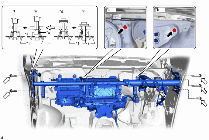
*1 Instrument Panel Reinforcement Assembly - - *a Movable Collar *b Vehicle Body *c Step 1 *d Step 2 *e Step 3 *f Step 4 Bolt A Bolt B 
Bolt C - - -
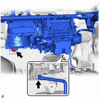
Disconnect the drain cooler hose.
-
Remove the nut and instrument panel reinforcement assembly with air conditioner unit assembly.
-
-
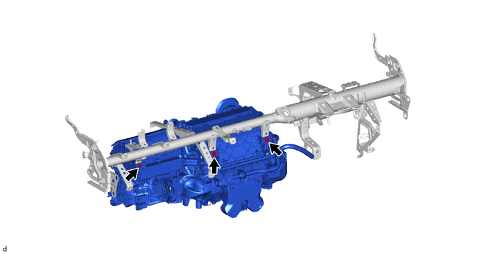
REMOVE AIR CONDITIONER UNIT ASSEMBLY
-
Remove the 3 bolts and air conditioner unit assembly from the instrument panel reinforcement assembly.
-