CLEARANCE WARNING BUZZER INSTALLATION
PROCEDURE
-
INSTALL NO. 1 CLEARANCE WARNING BUZZER
-
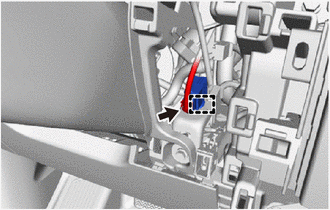
Engage the clamp to install the No. 1 clearance warning buzzer.
-
Connect the connector.
-
-
INSTALL NO. 1 SWITCH HOLE BASE
-
INSTALL INSTRUMENT CLUSTER FINISH PANEL SUB-ASSEMBLY
-
INSTALL LOWER NO. 2 INSTRUMENT PANEL FINISH PANEL
-
INSTALL NO. 1 INSTRUMENT PANEL UNDER COVER SUB-ASSEMBLY
-
INSTALL UPPER INSTRUMENT PANEL FINISH PANEL
-
INSTALL INSTRUMENT CLUSTER FINISH PANEL ASSEMBLY (for Separate Console Box Type)
-
INSTALL INSTRUMENT PANEL BOX ASSEMBLY (for Separate Console Box Type)
-
INSTALL CENTER NO. 2 INSTRUMENT CLUSTER FINISH PANEL (for Separate Console Box Type)
-
INSTALL CENTER NO. 1 INSTRUMENT CLUSTER FINISH PANEL (for Separate Console Box Type)
-
INSTALL CONSOLE BOX ASSEMBLY (for Integrated Type)