BLIND SPOT MONITOR SYSTEM, Diagnostic DTC:C1ABE
| DTC Code | DTC Name |
|---|---|
| C1ABE | Short to GND or Open in Buzzer |
DESCRIPTION
-
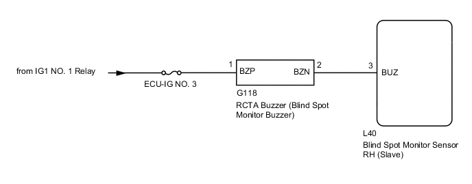
DTC C1ABE is stored when the blind spot monitor sensor RH (Slave) detects a short to ground or open in the RCTA buzzer (blind spot monitor buzzer) circuit.
| DTC No. | Detection Item | DTC Detection Condition | Trouble Area |
|---|---|---|---|
| C1ABE | Short to GND or Open in Buzzer |
Both of the following conditions are met: |
|
WIRING DIAGRAM
CAUTION / NOTICE / HINT
Note
-
When checking for DTCs, make sure that the blind spot monitor system is turned on.
-
Inspect the fuses for circuits related to this system before performing the following procedure.
PROCEDURE
-
CHECK DTC
-
Turn the engine switch off.
-
Turn the engine switch on (IG).
-
Recheck for DTCs and check if the same DTC is output again.
Body Electrical > Blind Spot Monitor Slave > Trouble CodesOK No DTCs are output. Result Proceed to OK NG
OK 
USE SIMULATION METHOD TO CHECK Click here
NG 
-
-
CHECK HARNESS AND CONNECTOR (RCTA BUZZER - BATTERY AND BLIND SPOT MONITOR SENSOR RH (SLAVE))
-
Disconnect the G118 RCTA buzzer (blind spot monitor buzzer) connector.
-
Disconnect the L40 blind spot monitor sensor RH (Slave) connector.
-
Measure the resistance according to the value(s) in the table below.
Standard Resistance Tester Connection Condition Specified Condition G118-2 (BZN) - L40-3 (BUZ) Always Below 1 Ω G118-2 (BZN) - Body ground Always 10 kΩ or higher -
Reconnect the L40 blind spot monitor sensor RH (Slave) connector.
-
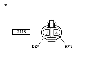
*a Front view of wire harness connector
(to RCTA Buzzer (Blind Spot Monitor Buzzer))
Measure the voltage according to the value(s) in the table below.
Standard Voltage Tester Connection Switch Condition Specified Condition G118-1 (BZP) - Body ground Engine switch on (IG) 11 to 14 V G118-1 (BZP) - Body ground Engine switch off Below 1 V Result Proceed to OK NG
NG
REPAIR OR REPLACE HARNESS OR CONNECTOR
OK
-
-
REPLACE RCTA BUZZER (BLIND SPOT MONITOR BUZZER)
-
Replace the RCTA buzzer (blind spot monitor buzzer).
Result Proceed to NEXT
NEXT
-
-
CHECK DTC
-
Clear the DTCs.
Body Electrical > Blind Spot Monitor Slave > Clear DTCs -
Recheck for DTCs and check if the same DTC is output again.
Body Electrical > Blind Spot Monitor Slave > Trouble CodesOK No DTCs are output. Result Proceed to OK NG
OK
END
NG
REPLACE BLIND SPOT MONITOR SENSOR RH (SLAVE) Click here
-