NAVIGATION ANTENNA CORD REMOVAL
CAUTION / NOTICE / HINT
The necessary procedures (adjustment, calibration, initialization or registration) that must be performed after parts are removed, installed or replaced during the navigation receiver removal/installation are shown below.
| Replacement Part or Procedure | Necessary Procedures | Effects/Inoperative Functions when not Performed | Link |
|---|---|---|---|
| Disconnect cable from negative battery terminal | Correct the steering angle neutral point | Panoramic view monitor system | |
| Initialize servo motor | Air conditioning system | ||
| Reset slide door close position | Power slide door system | ||
| Reset back door close position | Power back door system |
PROCEDURE
-
REMOVE ROOF HEADLINING ASSEMBLY
-
REMOVE NO. 1 DIGITAL TELEVISION ANTENNA SUB-ASSEMBLY (for Sliding Roof)
-
Disconnect the front pillar side connectors.
-
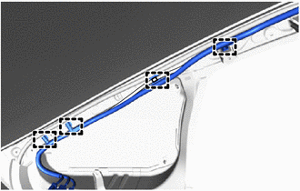
Disengage the clamps.
-
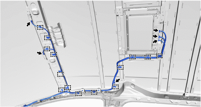
w/ Navigation System:
-
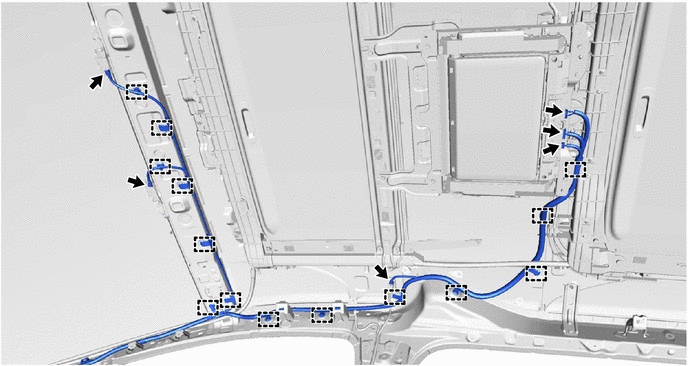
Disconnect the 6 connectors.
-
Disengage the clamps to remove the No. 1 digital television antenna sub-assembly.
-
-
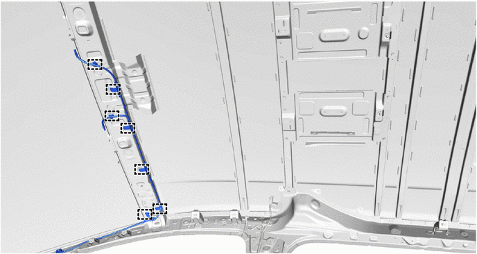
w/o Navigation System:
-
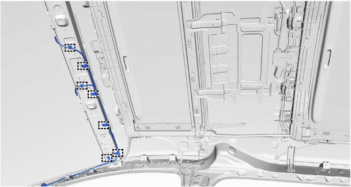
Disengage the clamps to remove the No. 1 digital television antenna sub-assembly.
-
-
-
REMOVE NO. 1 DIGITAL TELEVISION ANTENNA SUB-ASSEMBLY (for Normal Roof)
-
Disconnect the front pillar side connectors.
-
Disengage the clamps.
-
w/ Navigation System:
-
Disconnect the 6 connectors.
-
Disengage the clamps to remove the No. 1 digital television antenna sub-assembly.
-
-
w/o Navigation System:
-
Disengage the clamps to remove the No. 1 digital television antenna sub-assembly.
-
-
-
REMOVE CONSOLE BOX ASSEMBLY
-
REMOVE FRONT SEAT ASSEMBLY RH
-
REMOVE REAR NO. 1 SEAT ASSEMBLY RH
-
for Manual Captain Seat:
-
for Power Captain Seat with Memory:
-
for Power Captain Seat without Memory:
-
-
REMOVE REAR SEAT TRACK SLIDE STOPPER
-
REMOVE REAR SEAT LOCK STRIKER COVER
-
REMOVE NO. 3 FLOOR CARPET MOULDING
-
REMOVE NO. 4 FLOOR CARPET MOULDING (for Power Captain Seat)
-
REMOVE NO. 4 FLOOR CARPET MOULDING (for Super Long Slide Seat)
-
REMOVE LOWER NO. 1 SEAT TRACK RAIL PROTECTOR
-
REMOVE LOWER NO. 2 SEAT TRACK RAIL PROTECTOR
-
REMOVE LOWER SEAT TRACK RAIL PROTECTOR
-
REMOVE REAR OUTER SEAT TRACK ASSEMBLY RH
-
REMOVE NO. 4 ANTENNA CORD SUB-ASSEMBLY
-
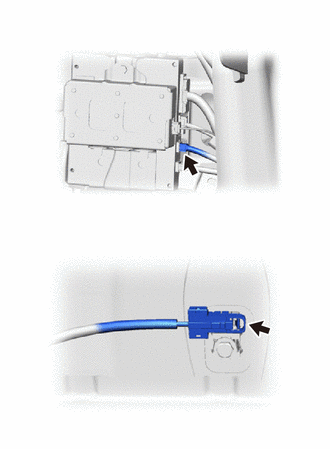
Disconnect the 2 connectors.
-
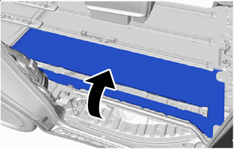

Peel back Peel back the rear floor mat assembly RH as shown in the illustration.
Note
Do not use excessive force when peeling back the rear floor mat assembly RH.
-
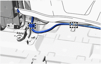
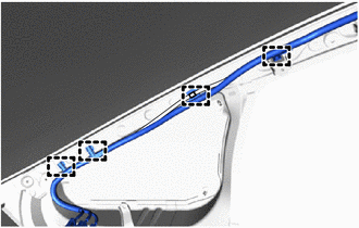
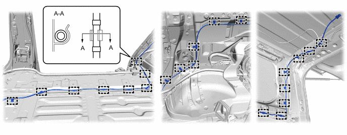
Disengage the clamps.
Note
Do not use excessive force when peeling back the rear floor mat assembly RH.
-
Disengage the clamps to remove the No. 4 antenna cord assembly as shown in the illustration.
-