NAVIGATION SYSTEM(for Navigation Receiver Type), Diagnostic DTC:B15D5
| DTC Code | DTC Name |
|---|---|
| B15D5 | Rear Seat Entertainment System Disconnected |
DESCRIPTION
w/ Panoramic View Monitor System
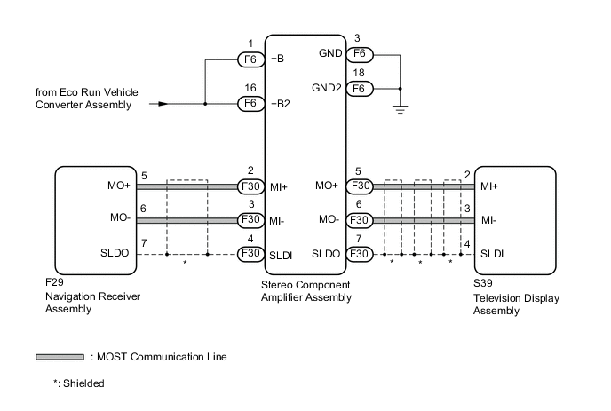
The navigation receiver assembly and television display assembly are connected by the MOST communication line.
When a MOST communication error occurs between the navigation receiver assembly and television display assembly, this DTC will be stored.
w/o Panoramic View Monitor System
The navigation receiver assembly and television display assembly are connected by the AVC-LAN communication line.
When an AVC-LAN communication error occurs between the navigation receiver assembly and television display assembly, this DTC will be stored.
| DTC No. | Detection Item | DTC Detection Condition | Trouble Area |
|---|---|---|---|
| B15D5 | Rear Seat Entertainment System Disconnected | w/ Panoramic View Monitor System
w/o Panoramic View Monitor System Any of the following conditions is met:
|
w/ Panoramic View Monitor System
w/o Panoramic View Monitor System
|
| Vehicle Condition | |||
|---|---|---|---|
| Pattern 1 | Pattern 2 | ||
| Diagnosis Condition | The engine switch is/was on (IG or ACC) | ○ | - |
| The engine is/was started | - | ○ | |
| Malfunction Status | Television display assembly is/was not connected | ○ | - |
| Communication between the master unit and the television display assembly is/was not possible | - | ○ | |
| Detection Time | - | - | |
| Number of Trips | 1 trip | 1 trip | |
Tech Tips
DTC will be output when conditions for either of the patterns in the table above are met.
Tech Tips
w/ Panoramic View Monitor System
-
For the MOST network, the navigation receiver assembly is the master unit.
w/o Panoramic View Monitor System
-
Even if no fault is present, this DTC may be stored depending on the battery condition or engine start voltage.
-
The navigation receiver assembly is the master unit.
WIRING DIAGRAM
-
w/ Panoramic View Monitor System
-
w/o Panoramic View Monitor System
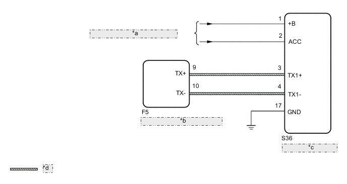
*a from Engine Stop and Start ECU *b Navigation Receiver Assembly *c Television Display Assembly *d AVC-LAN Communication Line
CAUTION / NOTICE / HINT
Note
-
Inspect the fuses for circuits related to this system before performing the following procedure.
-
Depending on the parts that are replaced during vehicle inspection or maintenance, performing initialization, registration or calibration may be needed. Refer to Precaution for Navigation System.
PROCEDURE
-
CONFIRM MODEL
-
Choose the model to be inspected.
Result Result Proceed to w/ Panoramic View Monitor System A w/o Panoramic View Monitor System B
B 
CHECK DTC Click here
A 
-
-
CHECK DTC
-
If DTC B15C3 is output, perform troubleshooting for DTC B15C3 first.
Result Result Proceed to DTC B15C3 is not output A DTC B15C3 is output B
B 
GO TO DTC B15C3 Click here
A
-
-
CHECK OPTIONAL COMPONENTS (INCLUDING ASSOCIATED WIRING)
-
Check that optional components (including associated wiring) which generate radio waves are not installed.
Result Result Proceed to Optional components (including associated wiring) are installed. A Optional components (including associated wiring) are not installed. B Tech Tips
-
Electrical noise from radio waves generated by optional components or the wiring for those components may affect MOST communication.
-
This DTC may be stored when an MOST communication error occurs due to electrical noise.
-
B
GO TO STEP 5 Click here
A
-
-
REMOVE OPTIONAL COMPONENTS (INCLUDING ASSOCIATED WIRING)
-
Remove optional components (including associated wiring).
Note
Do not remove optional components or associated wiring without the permission of the customer.
Result Proceed to NEXT
NEXT
-
-
CHECK DTC
-
Clear the DTCs.
Body Electrical > Navigation System > Clear DTCs -
Recheck for DTCs and check that no DTCs are output.
Body Electrical > Navigation System > Trouble CodesOK No DTCs are output. Result Proceed to OK NG
OK
END
NG
-
-
CHECK HARNESS AND CONNECTOR (TELEVISION DISPLAY ASSEMBLY POWER SOURCE)
-
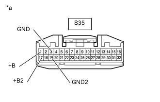
*a Front view of wire harness connector
(to Television Display Assembly)
Disconnect the television display assembly connector.
-
Measure the resistance according to the value(s) in the table below.
Standard Resistance Tester Connection Condition Specified Condition S35-3 (GND) - Body ground Always Below 1 Ω S35-19 (GND2) - Body ground Always Below 1 Ω -
Measure the voltage according to the value(s) in the table below.
Standard Voltage Tester Connection Condition Specified Condition S35-1 (+B) - S35-3 (GND) Always 11 to 14 V S35-17 (+B2) - S35-3 (GND) Always 11 to 14 V Result Result Proceed to OK A NG (except +B and +B2 circuit) B NG (for +B and +B2 circuit) (for 2AR-FE) C NG (for +B and +B2 circuit) (for 2GR-FKS) D
B
REPAIR OR REPLACE HARNESS OR CONNECTOR
C
GO TO STOP AND START SYSTEM Click here
D
GO TO STOP AND START SYSTEM Click here
A
-
-
CHECK HARNESS AND CONNECTOR (STEREO COMPONENT AMPLIFIER ASSEMBLY - TELEVISION DISPLAY ASSEMBLY)
-
Disconnect the F30 stereo component amplifier assembly connector.
-
Disconnect the S39 television display assembly connector.
-
Measure the resistance according to the value(s) in the table below.
Standard Resistance Tester Connection Condition Specified Condition F30-5 (MO+) - S39-2 (MI+) Always Below 1 Ω F30-6 (MO-) - S39-3 (MI-) Always Below 1 Ω F30-7 (SLDO) - S39-4 (SLDI) Always Below 1 Ω F30-5 (MO+) or S39-2 (MI+) - Body ground Always 10 kΩ or higher F30-6 (MO-) or S39-3 (MI-) - Body ground Always 10 kΩ or higher F30-7 (SLDO) or S39-4 (SLDI) - Body ground Always 10 kΩ or higher Result Proceed to OK NG
NG
REPAIR OR REPLACE HARNESS OR CONNECTOR
OK
-
-
CHECK HARNESS AND CONNECTOR (TELEVISION DISPLAY ASSEMBLY - NAVIGATION RECEIVER ASSEMBLY)
-
Disconnect the S39 television display assembly connector.
-
Disconnect the F29 navigation receiver assembly connector.
-
Measure the resistance according to the value(s) in the table below.
Standard Resistance Tester Connection Condition Specified Condition S39-5 (MO+) - F29-2 (MI+) Always Below 1 Ω S39-6 (MO-) - F29-3 (MI-) Always Below 1 Ω S39-7 (SLDO) - F29-4 (SLDI) Always Below 1 Ω S39-5 (MO+) or F29-2 (MI+) - Body ground Always 10 kΩ or higher S39-6 (MO-) or F29-3 (MI-) - Body ground Always 10 kΩ or higher S39-7 (SLDO) or F29-4 (SLDI) - Body ground Always 10 kΩ or higher Result Proceed to OK NG
NG
REPAIR OR REPLACE HARNESS OR CONNECTOR
OK
-
-
REPLACE TELEVISION DISPLAY ASSEMBLY
-
Replace the television display assembly.
-
Clear the DTCs.
Body Electrical > Navigation System > Clear DTCs -
Recheck for DTCs and check that no DTCs are output.
Body Electrical > Navigation System > Trouble CodesOK No DTCs are output. Result Proceed to OK NG
OK
END
NG
-
-
REPLACE STEREO COMPONENT AMPLIFIER ASSEMBLY
-
Replace the stereo component amplifier assembly.
-
Clear the DTCs.
Body Electrical > Navigation System > Clear DTCs -
Recheck for DTCs and check that no DTCs are output.
Body Electrical > Navigation System > Trouble CodesOK No DTCs are output. Result Proceed to OK NG
OK
END
NG
REPLACE NAVIGATION RECEIVER ASSEMBLY Click here
-
-
CHECK DTC
-
If DTC B15C3 is output, perform troubleshooting for DTC B15C3 first.
Result Result Proceed to DTC B15C3 is not output A DTC B15C3 is output B
B
GO TO DTC B15C3 Click here
A
-
-
CHECK OPTIONAL COMPONENTS (INCLUDING ASSOCIATED WIRING)
-
Check that optional components (including associated wiring) which generate radio waves are not installed.
Result Result Proceed to Optional components (including associated wiring) are installed. A Optional components (including associated wiring) are not installed. B Tech Tips
-
Electrical noise from radio waves generated by optional components or the wiring for those components may affect AVC-LAN communication.
-
This DTC may be stored when an AVC-LAN communication error occurs due to electrical noise.
-
B
GO TO STEP 14 Click here
A
-
-
REMOVE OPTIONAL COMPONENTS (INCLUDING ASSOCIATED WIRING)
-
Remove optional components (including associated wiring).
Note
Do not remove optional components or associated wiring without the permission of the customer.
Result Proceed to NEXT
NEXT
-
-
CHECK DTC
-
Clear the DTCs.
Body Electrical > Navigation System > Clear DTCs -
Recheck for DTCs and check that no DTCs are output.
Body Electrical > Navigation System > Trouble CodesOK No DTCs are output. Result Proceed to OK NG
OK
END
NG
-
-
CHECK HARNESS AND CONNECTOR (TELEVISION DISPLAY ASSEMBLY POWER SOURCE)
-
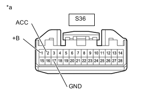
*a Front view of wire harness connector
(to Television Display Assembly)
Disconnect the television display assembly connector.
-
Measure the resistance according to the value(s) in the table below.
Standard Resistance Tester Connection Condition Specified Condition S36-17 (GND) - Body ground Always Below 1 Ω -
Measure the voltage according to the value(s) in the table below.
Standard Voltage Tester Connection Switch Condition Specified Condition S36-1 (+B) - S36-17 (GND) Always 11 to 14 V S36-2 (ACC) - S36-17 (GND) Engine switch on (ACC) 11 to 14 V Result Result Proceed to OK A NG (except +B and ACC circuit) B NG (for +B and ACC circuit) (for 2AR-FE) C NG (for +B and ACC circuit) (for 2GR-FKS) D
B
REPAIR OR REPLACE HARNESS OR CONNECTOR
C
GO TO STOP AND START SYSTEM Click here
D
GO TO STOP AND START SYSTEM Click here
A
-
-
CHECK HARNESS AND CONNECTOR (TELEVISION DISPLAY ASSEMBLY - NAVIGATION RECEIVER ASSEMBLY)
-
Disconnect the S36 television display assembly connector.
-
Disconnect the F5 navigation receiver assembly connector.
-
Measure the resistance according to the value(s) in the table below.
Standard Resistance Tester Connection Condition Specified Condition S36-3 (TX1+) - F5-9 (TX+) Always Below 1 Ω S36-4 (TX1-) - F5-10 (TX-) Always Below 1 Ω S36-3 (TX1+) or F5-9 (TX+) - Body ground Always 10 kΩ or higher S36-4 (TX1-) or F5-10 (TX-) - Body ground Always 10 kΩ or higher Result Proceed to OK NG
NG
REPAIR OR REPLACE HARNESS OR CONNECTOR
OK
-
-
REPLACE TELEVISION DISPLAY ASSEMBLY
-
Replace the television display assembly.
-
Clear the DTCs.
Body Electrical > Navigation System > Clear DTCs -
Recheck for DTCs and check that no DTCs are output.
Body Electrical > Navigation System > Trouble CodesOK No DTCs are output. Result Proceed to OK NG
OK
END
NG
REPLACE NAVIGATION RECEIVER ASSEMBLY Click here
-