NAVIGATION SYSTEM(for Navigation Receiver Type), Diagnostic DTC:B15D0
| DTC Code | DTC Name |
|---|---|
| B15D0 | MOST Communication Malfunction |
DESCRIPTION
This DTC is stored when the MOST network cannot be established after the master unit is activated.
| DTC No. | Detection Item | DTC Detection Condition | Trouble Area |
|---|---|---|---|
| B15D0 | MOST Communication Malfunction | MOST network cannot be established. |
|
Tech Tips
-
For the MOST network, the navigation receiver assembly is the master unit.
-
Errors may occur in MOST communication between devices due to problems such as electrical noise.
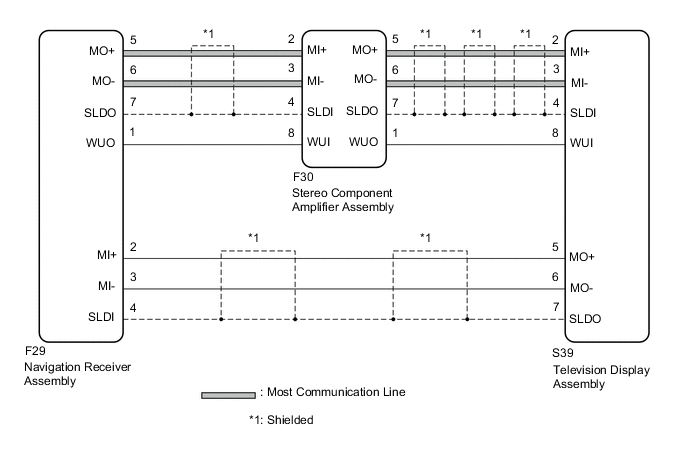
WIRING DIAGRAM
CAUTION / NOTICE / HINT
Note
Depending on the parts that are replaced during vehicle inspection or maintenance, performing initialization, registration or calibration may be needed. Refer to Precaution for Navigation System.
PROCEDURE
-
CHECK DTC
-
If DTC B15C3 is output, perform troubleshooting for DTC B15C3 first.
Result Result Proceed to DTC B15C3 is not output. A DTC B15C3 is output. B
B 
GO TO DTC B15C3 Click here
A 
-
-
PERFORM MOST LINE CHECK
-
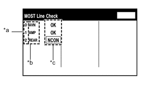
*a Node position number for devices that use MOST communication *b Device Name *c Result Display the "MOST Line Check" screen.
-
Check the result on the "MOST Line Check" screen.
Result Result Proceed to "NCON" is displayed for "AMP". A "NCON" is displayed for "REAR". B "OK" is displayed for all items. C Tech Tips
-
When "NCON" is displayed for more than 1 item, proceed to the step for the device that has the smallest node position number.
-
The "MOST Line Check" screen can be displayed only when DTC B15D0 is stored.
-
B 
CHECK COMMUNICATION CONNECTORS Click here
C
CHECK HARNESS AND CONNECTOR (NAVIGATION RECEIVER ASSEMBLY - STEREO COMPONENT AMPLIFIER ASSEMBLY) Click here
A
-
-
CHECK COMMUNICATION CONNECTORS
-
Check the MOST communication line connectors.
-
Check if the MOST communication line connector between the navigation receiver assembly and stereo component amplifier assembly has any connection problems.
-
-
Display the "MOST Line Check" screen and check the result.
Result Result Proceed to "NCON" is displayed for "AMP". A The screen cannot be changed to the "MOST Line Check" screen. B Tech Tips
When the malfunction in the MOST network is repaired, the screen cannot be changed to the "MOST Line Check" screen.
B
END
A
-
-
CHECK HARNESS AND CONNECTOR (WAKE-UP SIGNAL)
-
Disconnect the F30 stereo component amplifier assembly connector.
-
Measure the voltage according to the value(s) in the table below.
Standard Voltage Tester Connection Switch Condition Specified Condition F30-8 (WUI) - Body ground Engine switch on (ACC) 4.5 V or higher Result Proceed to OK NG
OK
REPLACE STEREO COMPONENT AMPLIFIER ASSEMBLY Click here
NG
-
-
CHECK HARNESS AND CONNECTOR (NAVIGATION RECEIVER ASSEMBLY - STEREO COMPONENT AMPLIFIER ASSEMBLY)
-
Disconnect the F29 navigation receiver assembly connector.
-
Disconnect the F30 stereo component amplifier assembly connector.
-
Measure the resistance according to the value(s) in the table below.
Standard Resistance Tester Connection Condition Specified Condition F30-8 (WUI) - F29-1 (WUO) Always Below 1 Ω F30-8 (WUI) or F29-1 (WUO) - Body ground Always 10 kΩ or higher Result Proceed to OK NG
OK
REPLACE NAVIGATION RECEIVER ASSEMBLY Click here
NG
REPAIR OR REPLACE HARNESS OR CONNECTOR
-
-
CHECK COMMUNICATION CONNECTORS
-
Check the MOST communication line connectors.
-
Check if the MOST communication line connector between the television display assembly and stereo component amplifier assembly has any connection problems.
-
-
Display the "MOST Line Check" screen and check the result.
Result Result Proceed to "NCON" is displayed for "REAR". A The screen cannot be changed to the "MOST Line Check" screen. B Tech Tips
When the malfunction in the MOST network is repaired, the screen cannot be changed to the "MOST Line Check" screen.
B
END
A
-
-
CHECK HARNESS AND CONNECTOR (WAKE-UP SIGNAL)
-
Disconnect the S39 television display assembly connector.
-
Measure the voltage according to the value(s) in the table below.
Standard Voltage Tester Connection Switch Condition Specified Condition S39-8 (WUI) - Body ground Engine switch on (ACC) 4.5 V or higher Result Proceed to OK NG
OK
REPLACE TELEVISION DISPLAY ASSEMBLY Click here
NG
-
-
CHECK HARNESS AND CONNECTOR (TELEVISION DISPLAY ASSEMBLY - STEREO COMPONENT AMPLIFIER ASSEMBLY)
-
Disconnect the S39 television display assembly connector.
-
Disconnect the F30 stereo component amplifier assembly connector.
-
Measure the resistance according to the value(s) in the table below.
Standard Resistance Tester Connection Condition Specified Condition S39-8 (WUI) - F30-1 (WUO) Always Below 1 Ω S39-8 (WUI) or F30-1 (WUO) - Body ground Always 10 kΩ or higher Result Proceed to OK NG
OK
REPLACE STEREO COMPONENT AMPLIFIER ASSEMBLY Click here
NG
REPAIR OR REPLACE HARNESS OR CONNECTOR
-
-
CHECK HARNESS AND CONNECTOR (NAVIGATION RECEIVER ASSEMBLY - STEREO COMPONENT AMPLIFIER ASSEMBLY)
-
Disconnect the F29 navigation receiver assembly connector.
-
Disconnect the F30 stereo component amplifier assembly connector.
-
Measure the resistance according to the value(s) in the table below.
Standard Resistance Tester Connection Condition Specified Condition F29-5 (MO+) - F30-2 (MI+) Always Below 1 Ω F29-6 (MO-) - F30-3 (MI-) Always Below 1 Ω F29-7 (SLDO) - F30-4 (SLDI) Always Below 1 Ω F29-1 (WUO) - F30-8 (WUI) Always Below 1 Ω F29-5 (MO+) or F30-2 (MI+) - Body ground Always 10 kΩ or higher F29-6 (MO-) or F30-3 (MI-) - Body ground Always 10 kΩ or higher F29-7 (SLDO) or F30-4 (SLDI) - Body ground Always 10 kΩ or higher F29-1 (WUO) or F30-8 (WUI) - Body ground Always 10 kΩ or higher Result Proceed to OK NG
NG
REPAIR OR REPLACE HARNESS OR CONNECTOR
OK
-
-
CHECK HARNESS AND CONNECTOR (TELEVISION DISPLAY ASSEMBLY - STEREO COMPONENT AMPLIFIER ASSEMBLY)
-
Disconnect the S39 television display assembly connector.
-
Disconnect the F30 stereo component amplifier assembly connector.
-
Measure the resistance according to the value(s) in the table below.
Standard Resistance Tester Connection Condition Specified Condition F30-5 (MO+) - S39-2 (MI+) Always Below 1 Ω F30-6 (MO-) - S39-3 (MI-) Always Below 1 Ω F30-7 (SLDO) - S39-4 (SLDI) Always Below 1 Ω F30-1 (WUO) - S39-8 (WUI) Always Below 1 Ω F30-5 (MO+) or S39-2 (MI+) - Body ground Always 10 kΩ or higher F30-6 (MO-) or S39-3 (MI-) - Body ground Always 10 kΩ or higher F30-7 (SLDO) or S39-4 (SLDI) - Body ground Always 10 kΩ or higher F30-1 (WUO) or S39-8 (WUI) - Body ground Always 10 kΩ or higher Result Proceed to OK NG
NG
REPAIR OR REPLACE HARNESS OR CONNECTOR
OK
-
-
CHECK HARNESS AND CONNECTOR (NAVIGATION RECEIVER ASSEMBLY - TELEVISION DISPLAY ASSEMBLY)
-
Disconnect the F29 navigation receiver assembly connector.
-
Disconnect the S39 television display assembly connector.
-
Measure the resistance according to the value(s) in the table below.
Standard Resistance Tester Connection Condition Specified Condition F29-2 (MI+) - S39-5 (MO+) Always Below 1 Ω F29-3 (MI-) - S39-6 (MO-) Always Below 1 Ω F29-4 (SLDI) - S39-7 (SLDO) Always Below 1 Ω F29-2 (MI+) or S39-5 (MO+) - Body ground Always 10 kΩ or higher F29-3 (MI-) or S39-6 (MO-) - Body ground Always 10 kΩ or higher F29-4 (SLDI) or S39-7 (SLDO) - Body ground Always 10 kΩ or higher Result Proceed to OK NG
NG
REPAIR OR REPLACE HARNESS OR CONNECTOR
OK
-
-
REPLACE TELEVISION DISPLAY ASSEMBLY
-
Replace the television display assembly.
-
Clear the DTCs.
Body Electrical > Navigation System > Clear DTCs -
Recheck for DTCs and check that no DTCs are output.
Body Electrical > Navigation System > Trouble CodesOK No DTCs are output. Result Proceed to OK NG
OK
END
NG
-
-
REPLACE STEREO COMPONENT AMPLIFIER ASSEMBLY
-
Replace the stereo component amplifier assembly.
-
Clear the DTCs.
Body Electrical > Navigation System > Clear DTCs -
Recheck for DTCs and check that no DTCs are output.
Body Electrical > Navigation System > Trouble CodesOK No DTCs are output. Result Proceed to OK NG
OK
END
NG
REPLACE NAVIGATION RECEIVER ASSEMBLY Click here
-