NOISE FILTER ON-VEHICLE INSPECTION
PROCEDURE
-
INSPECT RADIO SETTING CONDENSER
-
With the radio setting condenser installed, check that there is no looseness or other abnormalities.
-
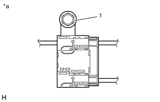
*a Radio Setting Condenser Measure the resistance of the radio setting condenser according to the value(s) in the table below.
Standard Resistance Tester Connection Condition Specified Condition 1 - Body ground
-
Engine switch off
-
High mounted stop light off
-
Window defogger off
Below 1 Ω -
-
Remove the bolt.
-
Disengage the clamp and disconnect the radio setting condenser with wire harness from the vehicle body.
-
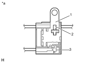
*a Radio Setting Condenser Measure the resistance and voltage of the radio setting condenser according to the value(s) in the table below.
Standard Resistance Tester Connection Condition Specified Condition 1 - 2
-
Engine switch off
-
High mounted stop light off
-
Window defogger off
10 kΩ or higher 1 - 3 10 kΩ or higher Standard Voltage Tester Connection Condition Specified Condition 2 - Body ground
-
Engine switch on (IG)
-
High mounted stop light off
Below 1 V 3 - Body ground
-
Engine switch on (IG)
-
Window defogger off
Below 1 V 2 - Body ground
-
Engine switch on (IG)
-
High mounted stop light on
11 to 14 V 3 - Body ground
-
Engine switch on (IG)
-
Window defogger on
11 to 14 V -
-