AMPLIFIER ANTENNA REMOVAL
CAUTION / NOTICE / HINT
The necessary procedures (adjustment, calibration, initialization or registration) that must be performed after parts are removed, installed or replaced during the amplifier antenna removal/installation are shown below.
| Replacement Part or Procedure | Necessary Procedures | Effects/Inoperative when not Performed | Link |
|---|---|---|---|
| Disconnect cable from negative battery terminal | Correct the steering angle neutral point | Panoramic view monitor system | |
| Initialize servo motor | Air conditioning system | ||
| Reset slide door close position | Power slide door system | ||
| Reset back door close position | Power back door system |
PROCEDURE
-
REMOVE REAR NO. 2 SEAT ASSEMBLY RH
-
REMOVE REAR NO. 3 FLOOR BOARD ASSEMBLY
-
REMOVE UTILITY BOX SUB-ASSEMBLY
-
REMOVE REAR NO. 1 FLOOR BOARD ASSEMBLY
-
REMOVE REAR NO. 2 FLOOR BOARD ASSEMBLY
-
REMOVE REAR BACK DOOR SCUFF PLATE
-
REMOVE REAR DOOR SCUFF PLATE RH
-
REMOVE REAR UPPER NO. 1 FLOOR BOARD PLATE
-
REMOVE NO. 1 LUGGAGE COMPARTMENT TRIM HOOK
-
REMOVE ROPE HOOK ASSEMBLY
-
REMOVE DECK SIDE GARNISH RH
-
REMOVE REAR QUARTER TRIM PANEL ASSEMBLY RH
-
REMOVE INNER UPPER ROOF SIDE GARNISH RH
-
REMOVE NO. 1 COOLER AIR DUCT
-
REMOVE NO. 1 AMPLIFIER ANTENNA ASSEMBLY
-
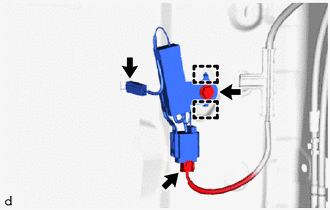
Disconnect the 2 connectors.
-
Remove the bolt.
-
Disengage the hooks to remove the No. 1 amplifier antenna assembly.
-