RADIO RECEIVER REMOVAL
CAUTION / NOTICE / HINT
The necessary procedures (adjustment, calibration, initialization or registration) that must be performed after parts are installed, removed or replaced during the radio receiver installation/removal are shown below.
| Replacement Part or Procedure | Necessary Procedures | Effects/Inoperative Functions when not Performed | Link |
|---|---|---|---|
| Disconnect cable from negative battery terminal | Correct the steering angle neutral point | Panoramic view monitor system | |
| Initialize servo motor | Air conditioning system | ||
| Reset slide door close position | Power slide door system | ||
| Reset back door close position | Power back door system |
PROCEDURE
-
PRECAUTION
Note
After turning the engine switch off, waiting time may be required before disconnecting the cable from the battery terminal. Therefore, make sure to read the disconnecting the cable from the battery terminal notice before proceeding with work.
-
DISCONNECT CABLE FROM NEGATIVE BATTERY TERMINAL
CAUTION:
Wait at least 90 seconds after disconnecting the cable from the negative (-) battery terminal to disable the SRS system.
Note
When disconnecting the cable, some systems need to be initialized after the cable is reconnected.
-
REMOVE CENTER NO. 1 INSTRUMENT CLUSTER FINISH PANEL (for Separate Console Box Type)
-
REMOVE CENTER NO. 2 INSTRUMENT CLUSTER FINISH PANEL (for Separate Console Box Type)
Tech Tips
Use the same procedure as for the center No. 1 instrument cluster finish panel. (for Separate Console Box Type)
-
REMOVE NO. 2 BOX BOTTOM MAT (for Integrated Console Box Type)
-
REMOVE INSTRUMENT PANEL FINISH PANEL END LH (for Integrated Console Box Type)
-
REMOVE INSTRUMENT PANEL FINISH PANEL END RH (for Integrated Console Box Type)
Tech Tips
Use the same procedure as for the instrument panel finish panel end LH. (for Integrated Console Box Type)
-
REMOVE UPPER INSTRUMENT PANEL FINISH PANEL
-
REMOVE NO. 3 INSTRUMENT PANEL REGISTER ASSEMBLY
-
REMOVE NO. 4 INSTRUMENT PANEL REGISTER ASSEMBLY
Tech Tips
Use the same procedure as for the No. 3 instrument panel register assembly.
-
REMOVE RADIO RECEIVER ASSEMBLY WITH BRACKET
-
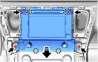

Remove in this Direction Remove the 4 bolts.
-
Disengage the claws to pull the radio receiver assembly with bracket as shown in the illustration.
-
Disconnect the connectors to remove the radio receiver assembly with bracket.
-
-
REMOVE NAVIGATION ECU WITH WIRE (w/ Navigation System)
-
REMOVE NO. 1 RADIO RECEIVER BRACKET
-
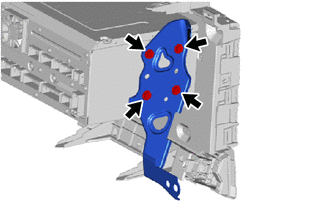
Remove the 4 screws and No. 1 radio receiver bracket.
-
-
REMOVE NO. 2 RADIO RECEIVER BRACKET
-
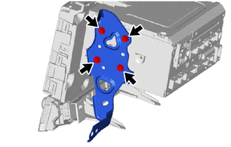
Remove the 4 screws and No. 2 radio receiver bracket.
-
-
REMOVE RADIO AND DISPLAY ASSEMBLY