REAR SEAT ENTERTAINMENT SYSTEM(for 12 Inch) Visual Mute Signal Circuit between Navigation ECU and Television Display
DESCRIPTION
This is the visual mute signal circuit from the navigation receiver assembly to the television display assembly.
WIRING DIAGRAM
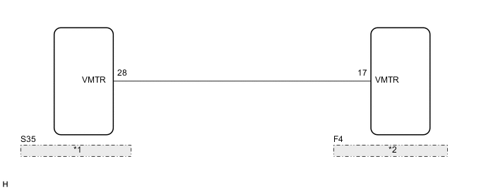
| *1 | Television Display Assembly |
| *2 | Navigation Receiver Assembly |
PROCEDURE
-
INSPECT NAVIGATION RECEIVER ASSEMBLY
-
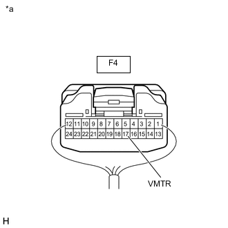
*a Component with harness connected
(Navigation Receiver Assembly)
Measure the voltage according to the value(s) in the table below.
Standard Voltage Tester Connection Condition Specified Condition F4-17 (VMTR) - Body ground RSE is playing → Source is changed Above 3.5 V → Below 1 V Result Proceed to OK NG
OK 
PROCEED TO NEXT SUSPECTED AREA SHOWN IN PROBLEM SYMPTOMS TABLE Click here
NG 
-
-
CHECK HARNESS AND CONNECTOR (TELEVISION DISPLAY ASSEMBLY - NAVIGATION RECEIVER ASSEMBLY)
-
Disconnect the F4 navigation receiver assembly connector.
-
Disconnect the S35 television display assembly connector.
-
Measure the resistance according to the value(s) in the table below.
Standard Resistance Tester Connection Condition Specified Condition F4-17 (VMTR) - S35-28 (VMTR) Always Below 1 Ω F4-17 (VMTR) or S35-28 (VMTR) - Body ground Always 10 kΩ or higher Result Proceed to OK NG
NG
REPAIR OR REPLACE HARNESS OR CONNECTOR
OK
-
-
INSPECT TELEVISION DISPLAY ASSEMBLY
-
Reconnect the S35 television display assembly connector.
-
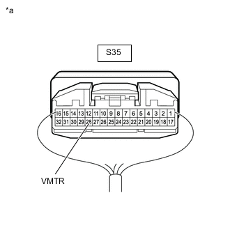
*a Rear view of wire harness connector
(to Television Display Assembly)
Measure the voltage according to the value(s) in the table below.
Standard Voltage Tester Connection Condition Specified Condition S35-28 (VMTR) - Body ground Display is operating Above 3.5 V Result Proceed to OK NG
OK
REPLACE NAVIGATION RECEIVER ASSEMBLY Click here
NG
REPLACE TELEVISION DISPLAY ASSEMBLY Click here
-