AUDIO AND VISUAL SYSTEM(for Radio and Display Type) Mute Signal Circuit between Radio Receiver and Telematics Transceiver
DESCRIPTION
The telematics transceiver sends a mute signal to the radio and display receiver assembly.
The radio and display receiver assembly controls the volume according to the mute signal from the telematics transceiver.
WIRING DIAGRAM
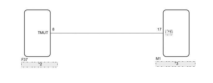
| *1 | MUTE |
| *2 | Radio and Display Receiver Assembly |
| *3 | Telematics Transceiver |
PROCEDURE
-
INSPECT TELEMATICS TRANSCEIVER
-
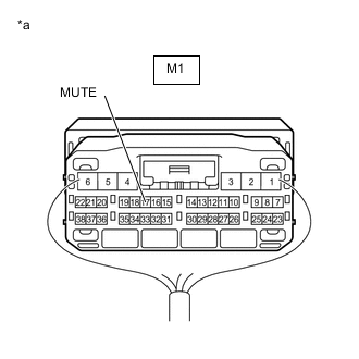
*a Component with harness connected
(Telematics Transceiver)
Measure the voltage according to the value(s) in the table below.
Standard Voltage Tester Connection Switch Condition Specified Condition M1-17 (MUTE) - Body ground Engine switch on (ACC)
Audio system playing
→ Emergency call mode
2.0 V or higher
→ Below 1 V
Result Proceed to OK NG
OK 
PROCEED TO NEXT SUSPECTED AREA SHOWN IN PROBLEM SYMPTOMS TABLE Click here
NG 
-
-
CHECK HARNESS AND CONNECTOR (RADIO AND DISPLAY RECEIVER ASSEMBLY - TELEMATICS TRANSCEIVER)
-
Disconnect the F37 radio and display receiver assembly connector.
-
Disconnect the M1 telematics transceiver connector.
-
Measure the resistance according to the value(s) in the table below.
Standard Resistance Tester Connection Condition Specified Condition F37-8 (TMUT) - M1-17 (MUTE) Always Below 1 Ω F37-8 (TMUT) - Body ground Always 10 kΩ or higher Result Proceed to OK NG
NG
REPAIR OR REPLACE HARNESS OR CONNECTOR
OK
-
-
INSPECT RADIO AND DISPLAY RECEIVER ASSEMBLY
-
Reconnect the F37 radio and display receiver assembly connector.
-
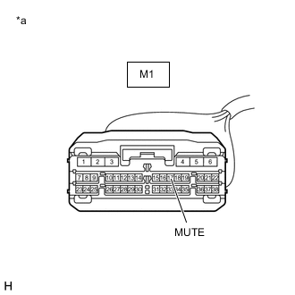
*a Front view of wire harness connector
(to Telematics Transceiver)
Measure the voltage according to the value(s) in the table below.
Standard Voltage Tester Connection Switch Condition Specified Condition M1-17 (MUTE) - Body ground Engine switch on (ACC) 2.0 V or higher Result Proceed to OK NG
OK
REPLACE TELEMATICS TRANSCEIVER Click here
NG
REPLACE RADIO AND DISPLAY RECEIVER ASSEMBLY Click here
-