STEERING GEAR INSTALLATION

PROCEDURE
-
INSTALL TIE ROD END SUB-ASSEMBLY LH
-
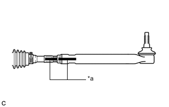
*a Matchmark Install the lock nut and tie rod end sub-assembly LH to the steering gear assembly until the matchmarks are aligned.
Tech Tips
After adjusting the toe-in, tighten the lock nut.
-
-
INSTALL TIE ROD END SUB-ASSEMBLY RH
Tech Tips
Perform the same procedure as for the LH side.
-
INSTALL STEERING LINK ASSEMBLY
-
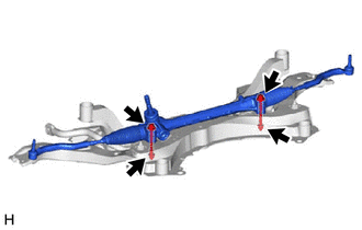
Install the steering link assembly to the front suspension crossmember sub-assembly with the 2 bolts and 2 nuts.
- Torque:
- 110 N*m { 1122 kgf*cm, 81 ft.*lbf }
Note
-
Because the nut has its own stopper, do not turn the nut. Tighten the bolt with the nut secured.
-
Make sure to tighten the bolts starting from the right side of the vehicle.
-
-
INSTALL STEERING INTERMEDIATE SHAFT
-
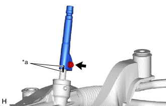
*a Matchmark Align the matchmarks and install the steering intermediate shaft to the steering link assembly.
-
Install a new bolt.
- Torque:
- 64 N*m { 653 kgf*cm, 47 ft.*lbf }
-
-
INSTALL NO. 1 STEERING COLUMN HOLE COVER SUB-ASSEMBLY
-
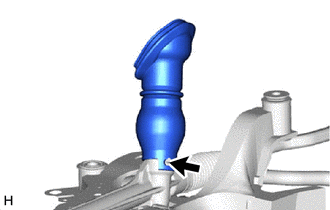
Align the protrusion of the steering link assembly with the hole of the No. 1 steering column hole cover sub-assembly, and install the No. 1 steering column hole cover sub-assembly to the steering link assembly.
Tech Tips
Check that the No. 1 steering column hole cover sub-assembly is securely installed.
-
-
INSTALL FRONT SUSPENSION CROSSMEMBER SUB-ASSEMBLY
-
INSTALL FRONT SUSPENSION MEMBER BRACE SUB-ASSEMBLY LH
-
INSTALL FRONT SUSPENSION MEMBER BRACE SUB-ASSEMBLY RH
Tech Tips
Perform the same procedure as for the LH side.
-
INSTALL FRONT SUSPENSION MEMBER REINFORCEMENT LH
-
INSTALL FRONT SUSPENSION MEMBER REINFORCEMENT RH
Tech Tips
Perform the same procedure as for the LH side.
-
CONNECT FRONT LOWER NO. 1 SUSPENSION ARM SUB-ASSEMBLY LH
-
CONNECT FRONT LOWER NO. 1 SUSPENSION ARM SUB-ASSEMBLY RH
Tech Tips
Perform the same procedure as for the LH side.
-
CONNECT TIE ROD END SUB-ASSEMBLY LH
-
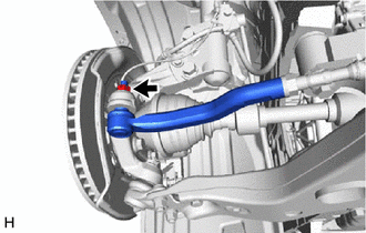
Connect the tie rod end sub-assembly LH to the steering knuckle LH with the nut.
- Torque:
- 49 N*m { 500 kgf*cm, 36 ft.*lbf }
Note
-
Do not damage the ball joint dust cover.
-
Further tighten the nut up to 60° if the holes for the cotter pin are not aligned.
-
Install a new cotter pin.
-
-
CONNECT TIE ROD END SUB-ASSEMBLY RH
Tech Tips
Perform the same procedure as for the LH side.
-
CONNECT FRONT STABILIZER LINK ASSEMBLY LH
-
CONNECT FRONT STABILIZER LINK ASSEMBLY RH
Tech Tips
Perform the same procedure as for the LH side.
-
CONNECT NO. 1 STEERING COLUMN HOLE COVER SUB-ASSEMBLY
-
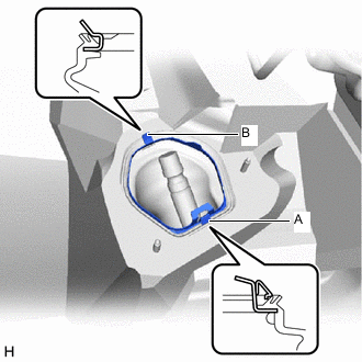
Engage the clip (B) to the vehicle body.
-
Engage the clip (A) to install the No. 1 steering column hole cover sub-assembly to the vehicle body.
Note
Be careful no to damage the lip of the No. 1 steering column hole cover sub-assembly.
-
-
CONNECT NO. 2 STEERING INTERMEDIATE SHAFT ASSEMBLY
-
INSTALL COLUMN HOLE COVER SILENCER SHEET
-
INSTALL REAR ENGINE UNDER COVER LH
for 2AR-FE: Click here
for 2GR-FKS: Click here
-
INSTALL REAR ENGINE UNDER COVER RH
for 2AR-FE: Click here
for 2GR-FKS: Click here
-
INSTALL NO. 2 ENGINE UNDER COVER (for Front Side)
for 2AR-FE: Click here
for 2GR-FKS: Click here
-
INSTALL NO. 2 ENGINE UNDER COVER (for Rear Side)
-
INSTALL NO. 1 ENGINE UNDER COVER
for 2AR-FE: Click here
for 2GR-FKS: Click here
-
INSTALL FRONT LOWER BUMPER ABSORBER
-
INSTALL FRONT BUMPER COVER
for ALPHARD: Click here
for VELLFIRE: Click here
-
INSTALL FRONT WHEELS
-
STABILIZE SUSPENSION
-
INSPECT AND ADJUST FRONT WHEEL ALIGNMENT
-
PERFORM INITIALIZATION
-
Initialization of the headlight ECU sub-assembly LH.
-
-
ADJUST FOG LIGHT AIMING