STEERING PAD SWITCH REMOVAL
CAUTION / NOTICE / HINT
The necessary procedures (adjustment, calibration, initialization, or registration) that must be performed after parts are removed, installed, or replaced during the steering pad switch assembly removal/installation are shown below.
| Replacement Part or Procedure | Necessary Procedures | Effects / Inoperative when not performed | Link |
|---|---|---|---|
| Disconnect cable from negative battery terminal | Drive the vehicle until stop and start control is permitted (approximately 15 to 40 minutes) | Stop and start system | |
| Memorize steering angle neutral point | Panoramic view monitor system | ||
| Initialize back door lock | Power door lock control system | ||
| Initialize servo motor | Air conditioning system | ||
| Reset slide door close position | Power Slide Door System | ||
| Reset back door close position | Power Back Door System |
PROCEDURE
-
REMOVE HORN BUTTON ASSEMBLY
-
REMOVE STEERING PAD SWITCH ASSEMBLY
-
Disconnect the steering pad switch connector from the spiral cable with sensor sub-assembly.
-
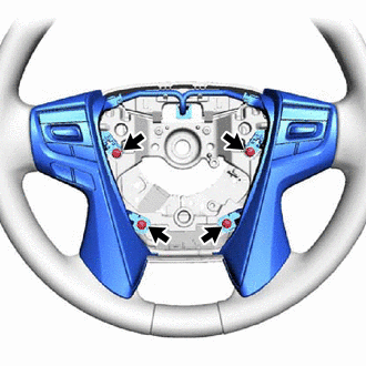
Remove the 4 screws.
-
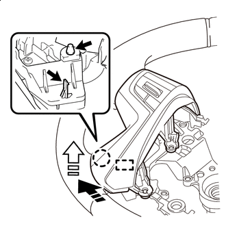

Remove in this Direction (1) 
Remove in this Direction (2) While pushing the steering pad switch assembly in the direction shown by the arrow (1) in the illustration to disengage the claw, pull the steering pad switch assembly in the direction shown by the arrow (2) in the illustration to disengage the guide pin.
-

Remove in this Direction (1) Remove in this Direction (2) While pushing the steering pad switch assembly in the direction shown by the arrow (1) in the illustration to disengage the claw, pull the steering pad switch assembly in the direction shown by the arrow (2) in the illustration to disengage the guide pin.
-
Remove the part from the steering wheel sub-assembly.
Tech Tips
Use the same procedure for both sides.
-