STEERING COLUMN ASSEMBLY INSTALLATION
PROCEDURE
-
ALIGN FRONT WHEELS FACING STRAIGHT AHEAD
-
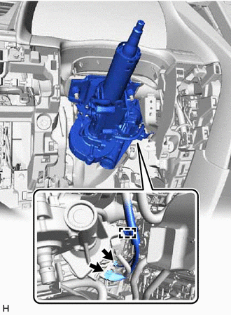
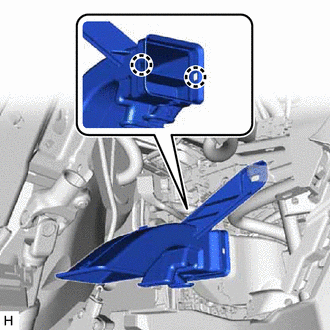
INSTALL STEERING COLUMN ASSEMBLY
Note
Make sure that the wire harness is not interfering with the steering column assembly.
-
Install the steering column assembly with the bolt and 2 nuts.
- Torque:
- 36 N*m { 367 kgf*cm, 27 ft.*lbf }
-
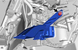
Connect each connector and engage each wire harness clamp to the steering column assembly.
-
Connect the 2 connectors.
-
Engage the clamp.
-
-
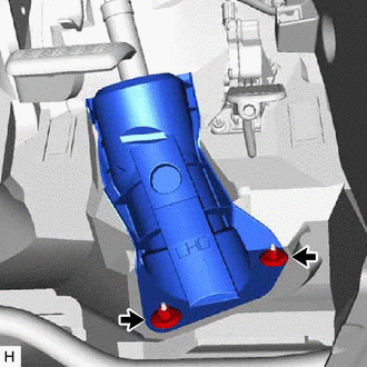
INSTALL BRAKE PEDAL SUPPORT ASSEMBLY
for LHD: Click here
for RHD: Click here
-
INSTALL NO. 2 STEERING INTERMEDIATE SHAFT ASSEMBLY
-
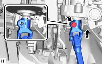
*a Matchmark Align the matchmarks on the No. 2 steering intermediate shaft assembly and steering column assembly.
-
Install the No. 2 steering intermediate shaft assembly to the steering column assembly.
-
Install a new bolt.
- Torque:
- 64 N*m { 653 kgf*cm, 47 ft.*lbf }
-
-
CONNECT NO. 2 STEERING INTERMEDIATE SHAFT ASSEMBLY
-
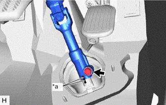
*a Matchmark Align the matchmarks on the No. 2 steering intermediate shaft assembly and steering intermediate shaft assembly.
-
Connect the No. 2 steering intermediate shaft assembly to the steering intermediate shaft assembly.
-
Install a new bolt.
- Torque:
- 64 N*m { 653 kgf*cm, 47 ft.*lbf }
-
-
INSTALL COLUMN HOLE COVER SILENCER SHEET
-
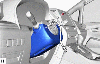
Install the column hole cover silencer sheet with 2 new clips.
-
Install the front floor mat to its original position.
-
-
INSTALL NO. 4 AIR DUCT SUB-ASSEMBLY
-
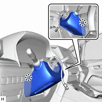
Engage the 2 claws to install the No. 4 air duct sub-assembly.
-
Install the clip.
-
-
INSTALL LOWER NO. 1 INSTRUMENT PANEL AIRBAG ASSEMBLY
-
INSTALL TURN SIGNAL SWITCH ASSEMBLY WITH SPIRAL CABLE SUB-ASSEMBLY
Note
-
Do not replace the spiral cable with sensor sub-assembly with the battery connected and the engine switch on (IG).
-
Do not rotate the spiral cable with sensor sub-assembly without the steering wheel assembly with the battery connected and the engine switch on (IG).
-
Ensure that the steering wheel assembly is installed and aligned straight when inspecting the steering sensor.
-
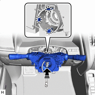

Install in this Direction Engage the 3 claws to install the turn signal switch assembly with spiral cable sub-assembly to the steering column assembly.
-
Connect each connector to the turn signal switch assembly with spiral cable sub-assembly.
-
-
INSTALL UPPER STEERING COLUMN COVER
-
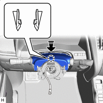
Install in this Direction Engage the 2 claws to install the upper steering column cover.
-
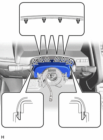
Engage the 6 clips to the upper steering column cover.
-
-
INSTALL LOWER STEERING COLUMN COVER
-
Engage the 2 claws to install the lower steering column cover.
-
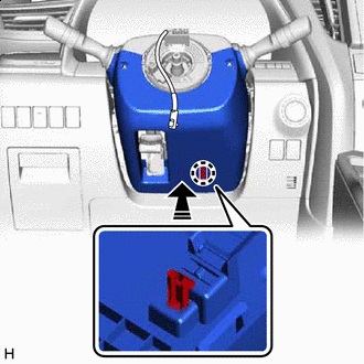
Install in this Direction Press the lower steering column cover to engage the claw to the steering column assembly.
Note
Make sure to engage the claw securely. If the claw is not engaged properly, the lower steering column cover may interfere with the steering wheel assembly.
Tech Tips
The claw is located inside the steering column cover.
-
Install the 2 screws.
- Torque:
- 2.0 N*m { 20 kgf*cm, 18 in.*lbf }
-
-
ALIGN FRONT WHEELS FACING STRAIGHT AHEAD
-
INSPECT AND ADJUST SPIRAL CABLE WITH SENSOR SUB-ASSEMBLY
-
INSTALL STEERING WHEEL ASSEMBLY
-
CHECK STEERING WHEEL CENTER POINT
-
INSTALL HORN BUTTON ASSEMBLY
-
PERFORM CALIBRATION OF TORQUE SENSOR ZERO POINT
-
ADJUST PANORAMIC VIEW MONITOR SYSTEM (w/ Panoramic View Monitor System)