STEERING COLUMN ASSEMBLY REMOVAL
CAUTION / NOTICE / HINT
The necessary procedures (adjustment, calibration, initialization, or registration) that must be performed after parts are removed, installed, or replaced during the electric power steering column sub-assembly removal/installation are shown below.
| Replacement Part or Procedure | Necessary Procedures | Effects / Inoperative when not performed | Link |
|---|---|---|---|
| Replacement of electric power steering column sub-assembly | Torque sensor zero point calibration |
|
|
| Removal/installation of the spiral cable with sensor sub-assembly | Steering angle neutral point (Initialize panoramic view monitor system) | Panoramic view monitor system | |
| Disconnect cable from negative battery terminal | Drive the vehicle until stop and start control is permitted (approximately 5 to 60 minutes) | Stop and Start System (for 2AR-FE) | |
| Stop and Start System (for 2GR-FKS) | |||
| Memorize steering angle neutral point | Panoramic view monitor system | ||
| Initialize back door lock | Power door lock control system | ||
| Initialize servo motor | Air conditioning system | ||
| Reset slide door close position | Power Slide Door System | ||
| Reset back door close position | Power Back Door System |
PROCEDURE
-
PRECAUTION
-
ALIGN FRONT WHEELS FACING STRAIGHT AHEAD
-
REMOVE HORN BUTTON ASSEMBLY
-
REMOVE STEERING WHEEL ASSEMBLY
-
REMOVE LOWER STEERING COLUMN COVER
-
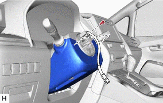
Remove the 2 screws.
-

Push Area While pressing the push area shown in the illustration to disengage the 2 claws, slightly lower the lower steering column cover.
-

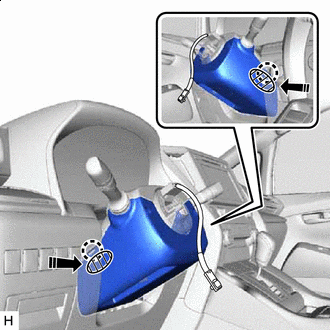
Removal in this Direction Disengage the claw and remove the lower steering column cover.
-
-
REMOVE UPPER STEERING COLUMN COVER
-
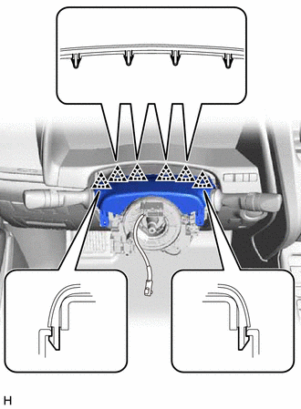
Disengage the 6 clips from the upper steering column cover.
-
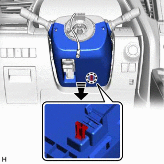
Removal in this Direction Disengage the 2 claws and remove the upper steering column cover.
-
-
REMOVE TURN SIGNAL SWITCH ASSEMBLY WITH SPIRAL CABLE SUB-ASSEMBLY
Note
-
Do not replace the spiral cable with sensor sub-assembly with the battery connected and the engine switch on (IG).
-
Do not rotate the spiral cable with sensor sub-assembly without the steering wheel assembly with the battery connected and the engine switch on (IG).
-
Ensure that the steering wheel assembly is installed and aligned straight when inspecting the steering sensor.
-
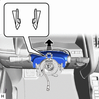
Disconnect each connector from the turn signal switch assembly with spiral cable sub-assembly.
-
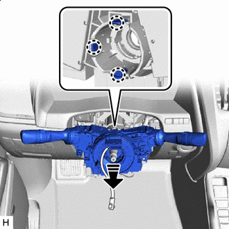
Removal in this Direction Disengage the 3 claws to remove the turn signal switch assembly with spiral cable sub-assembly from the steering column assembly.
-
-
REMOVE LOWER NO. 1 INSTRUMENT PANEL AIRBAG ASSEMBLY
-
REMOVE NO. 4 AIR DUCT SUB-ASSEMBLY
-
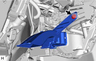
Remove the clip.
-
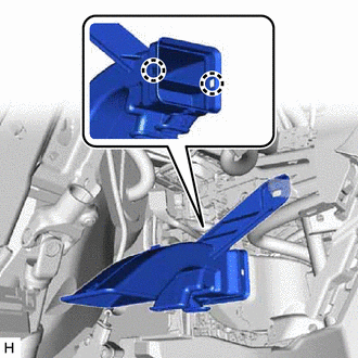
Disengage the 2 claws to remove the No. 4 air duct sub-assembly.
-
-
REMOVE COLUMN HOLE COVER SILENCER SHEET
-
Turn back the front floor mat.
-
Remove the 2 clips and column hole cover silencer sheet.
-
-
SEPARATE NO. 2 STEERING INTERMEDIATE SHAFT ASSEMBLY
-
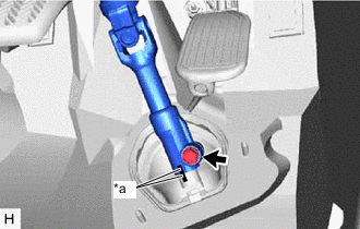
*a Matchmark Put matchmarks on the No. 2 steering intermediate shaft assembly and steering intermediate shaft assembly.
-
Remove the bolt.
-
Separate the No. 2 steering intermediate shaft assembly from the steering intermediate shaft assembly.
-
-
REMOVE NO. 2 STEERING INTERMEDIATE SHAFT ASSEMBLY
-
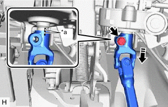
*a Matchmark Remove the bolt and slide the No. 2 steering intermediate shaft assembly.
Note
Do not remove the No. 2 steering intermediate shaft assembly from the steering column assembly.
-
Put matchmarks on the No. 2 steering intermediate shaft assembly and the steering column assembly.
-
Remove the No. 2 steering intermediate shaft assembly from the steering column assembly.
-
-
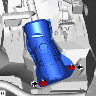
REMOVE BRAKE PEDAL SUPPORT ASSEMBLY
for LHD: Click here
for RHD: Click here
-
REMOVE STEERING COLUMN ASSEMBLY
-
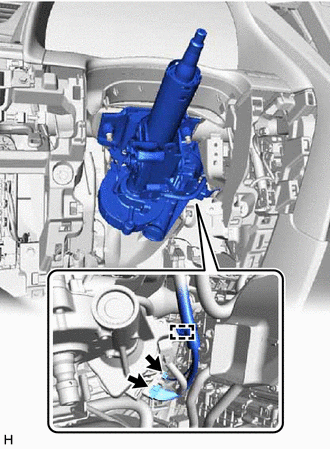
Disconnect the 2 connectors.
-
Disengage the clamp.
-
Disconnect each connector and disengage each wire harness clamp from the steering column assembly.
-
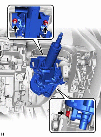
Remove the bolt, 2 nuts and steering column assembly.
-