ELECTRIC PARKING BRAKE ECU REMOVAL
CAUTION / NOTICE / HINT
The necessary procedures (adjustment, calibration, initialization, or registration) that must be performed after parts are removed, installed, or replaced during the parking brake ECU assembly removal/installation are shown below.
| Replacement Part or Procedure | Necessary Procedures | Effects/Inoperative when not Performed | Link |
|---|---|---|---|
| Disconnect cable from negative battery terminal | Drive the vehicle until stop and start control is permitted (approximately 15 to 40 minutes) | Stop and start system | |
| Memorize steering angle neutral point | Panoramic view monitor system | ||
| Initialize back door lock | Power door lock control system | ||
| Initialize servo motor | Air conditioning system | ||
| Reset slide door close position | Power Slide Door System | ||
| Reset back door close position | Power Back Door System | ||
| Parking brake ECU assembly | Operate the electric parking brake switch (combination switch assembly) | Parking brake indicator light (red) blinks when the engine switch is first turned on (IG). |
PROCEDURE
-
PRECAUTION
Note
-
Be sure to read Precaution thoroughly before servicing.
-
After turning the engine switch off, waiting time may be required before disconnecting the cable from the negative (-) battery terminal. Therefore, make sure to read the disconnecting the cable from the negative (-) battery terminal notices before proceeding with work.
-
-
DISCONNECT CABLE FROM NEGATIVE BATTERY TERMINAL
Note
When disconnecting the cable from the negative (-) battery terminal, some systems need to be initialized after the cable is reconnected.
-
REMOVE DECK SIDE TRIM COVER LH
-
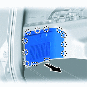

Remove in this Direction Disengage the 10 claws and 2 guides to remove the deck side trim cover LH.
-
-
REMOVE DECK TRIM SERVICE HOLE COVER
-
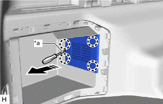
*a Protective Tape Remove in this Direction Using a screwdriver with its tip wrapped with protective tape, disengage the 4 claws and remove the deck trim service hole cover.
-
-
REMOVE PARKING BRAKE ECU ASSEMBLY
-
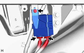
Disconnect the 2 connectors.
-
Remove the bolt and parking brake ECU assembly.
-