ELECTRIC PARKING BRAKE SYSTEM Electric Parking Brake does not Operate
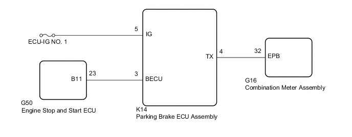
WIRING DIAGRAM
CAUTION / NOTICE / HINT
Note
-
Inspect the fuses for circuits related to this system before performing the following inspection procedure.
-
Before disconnecting connectors or fuses, turn the engine switch off and wait 20 seconds or more.
-
When replacing the parking brake ECU assembly, operate the electric parking brake switch (combination switch assembly) as the parking brake indicator light blinks (red) when the engine switch is first turned on (IG).
Tech Tips
Even if the electric parking brake is operating normally, the parking brake indicator light (red) on the combination meter may be malfunctioning.
PROCEDURE
-
VEHICLE OPERATION CHECK
-
Start the engine and move the shift lever to D. Then depress the brake pedal and pull the electric parking brake switch (combination switch assembly) to the lock side for 1 second. Check the parking brake indicator light (red) operation.
-
Release the brake pedal and check that the vehicle does not move.
-
Depress the brake pedal and push the electric parking brake switch (combination switch assembly) to the release side for 1 second. Check the parking brake indicator light (red) operation.
-
Release the brake pedal and check that the vehicle moves.
Result Result Proceed to Lock and release operation is normal and parking brake indicator light turns off or blinks (red) A Lock and release operation is malfunctioning and parking brake indicator light illuminates (red) or turns off according to switch operation B Lock and release operation is malfunctioning and parking brake indicator light turns off or blinks (red) C
B 
INSPECT REAR BRAKE
C 
CHECK HARNESS AND CONNECTOR (BECU CIRCUIT) Click here
A 
-
-
PERFORM ACTIVE TEST USING GTS (PKB LIGHT)
-
Turn the engine switch off.
-
Connect the GTS to the DLC3.
-
Turn the engine switch on (IG).
-
Turn the GTS on.
-
Enter the following menus: Chassis / Electric Parking Brake / Active Test.
-
Perform the Active Test according to the display on the GTS.
Chassis > Electric Parking Brake > Active TestTester Display Measurement Item Control Range Diagnostic Note PKB Light Parking brake indicator light (red) ON or OFF
-
Vehicle stopped
-
Engine switch on (IG)
-
Parking brake released
Chassis > Electric Parking Brake > Active TestTester Display PKB Light OK The parking brake indicator light turns on (red) or off in accordance with the Active Test operation. Result Proceed to OK NG -
OK
REPLACE PARKING BRAKE ECU ASSEMBLY Click here
NG
-
-
CHECK HARNESS AND CONNECTOR (PARKING BRAKE ECU ASSEMBLY - COMBINATION METER ASSEMBLY)
-
Turn the engine switch off.
-
Disconnect the K14 parking brake ECU assembly connector.
-
Disconnect the G16 combination meter assembly connector.
-
Measure the resistance according to the value(s) in the table below.
Standard Resistance Tester Connection Condition Specified Condition K14-4 (TX) - G16-32 (EPB) Always Below 1 Ω K14-4 (TX) or G16-32 (EPB) - Body ground Always 10 kΩ or higher Result Proceed to OK NG
OK
GO TO METER / GAUGE SYSTEM Click here
NG
REPAIR OR REPLACE HARNESS OR CONNECTOR
-
-
CHECK HARNESS AND CONNECTOR (BECU CIRCUIT)
-
Turn the engine switch off.
-
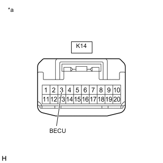
*a Front view of wire harness connector
(to Parking Brake ECU Assembly)
Disconnect the K14 parking brake ECU assembly connector.
-
Measure the voltage according to the value(s) in the table below.
Standard Voltage Tester Connection Condition Specified Condition K14-3 (BECU) - Body ground Always 10.5 to 16 V Result Proceed to OK NG
NG
GO TO STOP AND START SYSTEM (Backup Boost Converter Circuit) for 2AR-FE: Click here
GO TO STOP AND START SYSTEM (Backup Boost Converter Circuit) for 2GR-FKS: Click hereOK
-
-
CHECK HARNESS AND CONNECTOR (BATTERY - PARKING BRAKE ECU ASSEMBLY)
-
Turn the engine switch off.
-
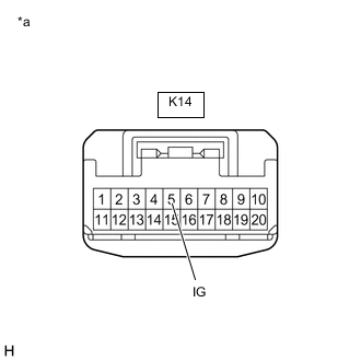
*a Front view of wire harness connector
(to Parking Brake ECU Assembly)
Disconnect the parking brake ECU assembly connector.
-
Measure the voltage according to the value(s) in the table below.
Standard Voltage Tester Connection Switch Condition Specified Condition K14-5 (IG) - Body ground Engine switch on (IG) 11 to 14 V Result Proceed to OK NG
OK
REPLACE PARKING BRAKE ECU ASSEMBLY Click here
NG
REPAIR OR REPLACE HARNESS OR CONNECTOR
-