ELECTRIC PARKING BRAKE SYSTEM, Diagnostic DTC:C13A2/22
| DTC Code | DTC Name |
|---|---|
| C13A2/22 | Engine / Power Switch Malfunction |
DESCRIPTION
When the engine switch is turned on (IG), power is supplied to the parking brake ECU assembly. This DTC is stored if IG power source voltage is not supplied to the parking brake ECU assembly when communication with other ECUs is established.
| DTC No. | Detection Item | DTC Detection Condition | Trouble Area | Memory | Note |
|---|---|---|---|---|---|
| C13A2/22 | Engine / Power Switch Malfunction | Both of following conditions are met:
|
|
DTC stored | An electric parking brake system malfunction is displayed on the multi-information display. |
WIRING DIAGRAM
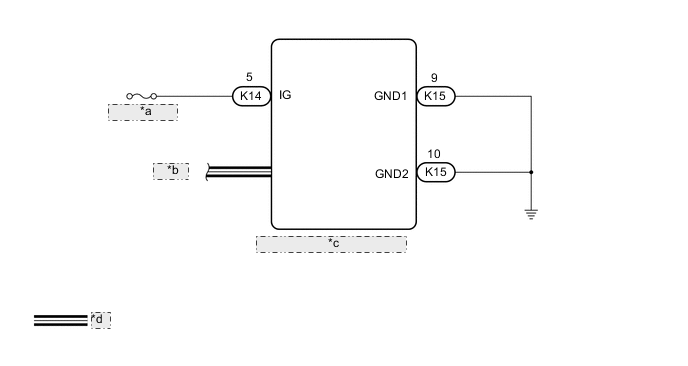
| *a | ECU-IG NO. 1 |
| *b | to CAN |
| *c | Parking Brake ECU Assembly |
| *d | CAN Communication Line |
CAUTION / NOTICE / HINT
Note
-
Inspect the fuses for circuits related to this system before performing the following inspection procedure.
-
Before disconnecting connectors or fuses, turn the engine switch off and wait 20 seconds or more.
-
When replacing the parking brake ECU assembly, operate the electric parking brake switch (combination switch assembly) as the parking brake indicator light (red) blinks when the engine switch is first turned on (IG).
PROCEDURE
-
READ VALUE USING GTS (IG STATUS / IG SWITCH)
-
Turn the engine switch off.
-
Connect the GTS to the DLC3.
-
Turn the engine switch on (IG).
-
Turn the GTS on.
-
Enter the following menus: Chassis / Electric Parking Brake / Data List.
-
Read the Data List according to the display on the GTS.
Chassis > Electric Parking Brake > Data ListTester Display Measurement Item Range Normal Condition IG Status Engine switch status ON or OFF ON: Engine switch is on (IG)
OFF: Engine switch is on (ACC) or off
IG Switch IG power source status ON or OFF ON: IG power source voltage is supplied to parking brake ECU assembly
OFF: IG power source voltage is not supplied to parking brake ECU assembly
Chassis > Electric Parking Brake > Data ListTester Display IG Status IG Switch Result Proceed to OK NG
NG 
CHECK HARNESS AND CONNECTOR (PARKING BRAKE ECU ASSEMBLY - INSTRUMENT PANEL JUNCTION BLOCK ASSEMBLY) Click here
OK 
-
-
CHECK DTC
-
Clear the DTCs.
Chassis > Electric Parking Brake > Clear DTCs -
Turn the engine switch off.
-
Check for DTCs.
Chassis > Electric Parking Brake > Trouble CodesResult Result Proceed to DTCs are output A DTCs are not output B
A 
REPLACE PARKING BRAKE ECU ASSEMBLY Click here
B
USE SIMULATION METHOD TO CHECK Click here
-
-
CHECK HARNESS AND CONNECTOR (PARKING BRAKE ECU ASSEMBLY - INSTRUMENT PANEL JUNCTION BLOCK ASSEMBLY)
-
Disconnect the K14 and K15 parking brake ECU assembly connectors.
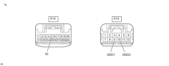
*a Front view of wire harness connector
(to Parking Brake ECU Assembly)
- - -
Turn the engine switch on (IG).
-
Measure the voltage according to the value(s) in the table below.
Standard Voltage Tester Connection Condition Specified Condition K14-5 (IG) - Body ground IG ON 8 to 16 V -
Turn the engine switch off.
-
Measure the resistance according to the value(s) in the table below.
Standard Resistance Tester Connection Condition Specified Condition K15-9 (GND1) - Body ground Always Below 1 Ω K15-10 (GND2) - Body ground Always Below 1 Ω Result Proceed to OK NG
OK
REPAIR IG POWER SOURCE CIRCUIT
NG
REPAIR OR REPLACE HARNESS OR CONNECTOR
-