VACUUM PUMP INSTALLATION
PROCEDURE
-
INSTALL VACUUM PUMP ASSEMBLY
-
When using a new vacuum pump assembly:
-
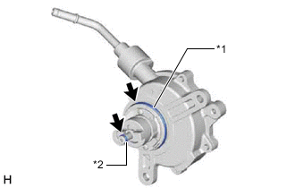
*1 No. 2 O-ring *2 No. 3 O-ring 
Engine Oil Apply engine oil to the No. 2 O-ring and No. 3 O-ring which are installed to a new vacuum pump assembly.
-
-
When reusing the vacuum pump assembly:
-
*1 No. 2 O-ring *2 No. 3 O-ring Engine Oil Apply engine oil to a new No. 2 O-ring and No. 3 O-ring and install them to the vacuum pump assembly.
-
-
Apply engine oil to the inner surface of the installation hole.
-
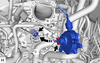
*a Coupling Teeth *b Groove *c Oil Pipe Temporarily install the vacuum pump assembly so that the oil pipe engages with the hole of the camshaft and the coupling teeth engages with the groove of the camshaft.
Note
-
Ensure that the vacuum pump assembly is installed securely.
-
Be careful not to pinch the O-ring.
-
-
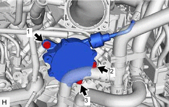
Install the vacuum pump assembly with the 3 bolts.
- Torque:
- 21 N*m { 214 kgf*cm, 15 ft.*lbf }
Note
-
After installation, check that there are no gaps between the matching surfaces and that the vacuum pump assembly is not installed at an angle.
-
Tighten the 3 bolts in the order shown in the illustration.
-
-
INSTALL ENGINE WIRE
-
Install the wiring harness clamp bracket with the bolt.
- Torque:
- 10 N*m { 102 kgf*cm, 7 ft.*lbf }
-
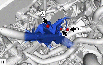
Install the engine wire with the 2 bolts and nut.
- Torque:
- Bolt (A)
- 10 N*m { 102 kgf*cm, 7 ft.*lbf }
- Bolt (B)
- 8.35 N*m { 85 kgf*cm, 74 in.*lbf }
- Nut
- 10 N*m { 102 kgf*cm, 7 ft.*lbf }
-
-
CONNECT AIR HOSE
-
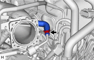
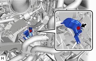
Connect the air hose to the vacuum pump assembly and slide the clip to secure it.
-
-
INSTALL NO. 2 SURGE TANK STAY
-
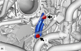
Install the No. 2 surge tank stay with the 2 bolts in the order shown in the illustration.
- Torque:
- 21 N*m { 214 kgf*cm, 15 ft.*lbf }
-
-
INSTALL AIR CLEANER CASE SUB-ASSEMBLY
-
INSTALL OUTER COWL TOP PANEL SUB-ASSEMBLY
for LHD: Click here
for RHD: Click here
-
INSTALL NO. 1 HEATER AIR DUCT SPLASH SHIELD SEAL
for LHD: Click here
for RHD: Click here
-
INSTALL NO. 2 HEATER AIR DUCT SPLASH SHIELD SEAL
for LHD: Click here
for RHD: Click here
-
INSTALL BRAKE MASTER CYLINDER RESERVOIR ASSEMBLY
for LHD: Click here
for RHD: Click here
-
INSTALL WINDSHIELD WIPER MOTOR AND LINK ASSEMBLY
for LHD: Click here
for RHD: Click here
-
INSPECT WASHER NOZZLE
-
INSTALL THROTTLE BODY WITH MOTOR ASSEMBLY
-
INSPECT VACUUM PUMP OPERATION