VACUUM PUMP REMOVAL
CAUTION / NOTICE / HINT
The necessary procedures (adjustment, calibration, initialization or registration) that must be performed after parts are removed and installed, or replaced during vacuum pump assembly removal/installation are shown below.
| Replacement Part or Procedure | Necessary Procedures | Effects/Inoperative when not Performed | Link |
|---|---|---|---|
| Disconnect cable from negative battery terminal | Drive the vehicle until stop and start control is permitted (approximately 5 to 60 minutes) | Stop and Start System | |
| Memorize steering angle neutral point | Panoramic View Monitor System | ||
| Initialize back door lock | Power Door Lock Control System | ||
| Initialize servo motor | Air Conditioning System | ||
| Reset slide door close position | Power Slide Door System | ||
| Reset back door close position | Power Back Door System |
PROCEDURE
-
PRECAUTION
Note
After turning the engine switch off, waiting time may be required before disconnecting the cable from the negative (-) battery terminal. Therefore, make sure to read the disconnecting the cable from the negative (-) battery terminal notices before proceeding with work.
-
REMOVE THROTTLE BODY WITH MOTOR ASSEMBLY
-
REMOVE WINDSHIELD WIPER MOTOR AND LINK ASSEMBLY
for LHD: Click here
for RHD: Click here
-
SEPARATE BRAKE MASTER CYLINDER RESERVOIR ASSEMBLY
for LHD: Click here
for RHD: Click here
-
REMOVE NO. 1 HEATER AIR DUCT SPLASH SHIELD SEAL
for LHD: Click here
for RHD: Click here
-
REMOVE NO. 2 HEATER AIR DUCT SPLASH SHIELD SEAL
for LHD: Click here
for RHD: Click here
-
REMOVE OUTER COWL TOP PANEL SUB-ASSEMBLY
for LHD: Click here
for RHD: Click here
-
REMOVE AIR CLEANER CASE SUB-ASSEMBLY
-
REMOVE NO. 2 SURGE TANK STAY
-
DISCONNECT AIR HOSE
-
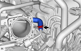
Slide the clip and disconnect the air hose from the vacuum pump assembly.
-
-
SEPARATE ENGINE WIRE
-
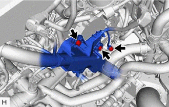
Remove the 2 bolts and nut to separate the engine wire.
-
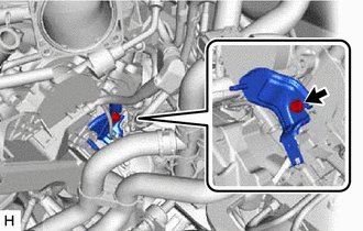
Remove the bolt and wiring harness clamp bracket from the engine assembly.
-
-
REMOVE VACUUM PUMP ASSEMBLY
-
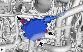
Remove the 3 bolts and vacuum pump assembly from the engine assembly.
-
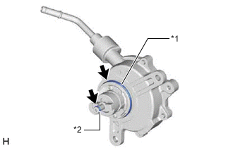
*1 No. 2 O-ring *2 No. 3 O-ring Remove the No. 2 O-ring and No. 3 O-ring from the vacuum pump assembly.
-