BRAKE BOOSTER(for RHD) REMOVAL
CAUTION / NOTICE / HINT
The necessary procedures (adjustment, calibration, initialization, or registration) that must be performed after parts are removed, installed, or replaced during the brake booster assembly removal/installation are shown below.
| Replacement Part or Procedure | Necessary Procedures | Effects/Inoperative when not Performed | Link |
|---|---|---|---|
| Disconnect cable from negative battery terminal | Drive the vehicle until stop and start control is permitted (approximately 5 to 60 minutes) | Stop and Start System (for 2AR-FE) | |
| Stop and Start System (for 2GR-FKS) | |||
| Memorize steering angle neutral point | Panoramic View Monitor System | ||
| Initialize back door lock | Power Door Lock Control System | ||
| Initialize servo motor | Air Conditioning System | ||
| Reset slide door close position | Power Slide Door System | ||
| Reset back door close position | Power Back Door System |
CAUTION / NOTICE / HINT
Note
Make sure to release vacuum from the brake booster assembly before removing the brake master cylinder sub-assembly from the brake booster assembly.
PROCEDURE
-
REMOVE BRAKE MASTER CYLINDER SUB-ASSEMBLY
-
REMOVE LOWER NO. 1 INSTRUMENT PANEL AIRBAG ASSEMBLY
-
REMOVE INTAKE AIR SURGE TANK ASSEMBLY (for 2GR-FKS)
-
SEPARATE UNION TO CHECK VALVE HOSE
-
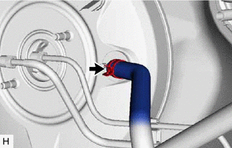
Slide the clip and disconnect the union to check valve hose from the brake booster assembly.
-
-
SEPARATE ENGINE ROOM MAIN WIRE
-
for 2GR-FKS:
-
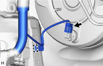
Disconnect the connector from the vacuum warning switch assembly.
-
Disengage the clamp and separate the wire harness.
-
-
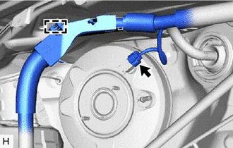
Disconnect the connector from the vacuum sensor.
-
Disengage the clamp and separate the engine room main wire.
-
-
SEPARATE BRAKE LINE
-
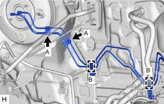
Remove the 2 clamps (A) from the 2 brake lines.
Note
Do not damage or deform the brake lines.
-
Disengage the 2 clamps (B) and separate the 2 brake lines.
Note
Do not damage or deform the brake lines.
-
-
LOOSEN CLEVIS LOCK NUT
-
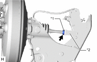
*1 Clevis Lock Nut *2 Brake Master Cylinder Push Rod Clevis Loosen the clevis lock nut of the brake master cylinder push rod clevis.
-
-
REMOVE BRAKE PEDAL RETURN SPRING
-
REMOVE PUSH ROD PIN
-
REMOVE BRAKE BOOSTER ASSEMBLY
-
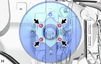
Remove the 4 nuts and push the brake booster assembly toward the engine compartment.
Note
Do not apply excessive force to the brake lines or refrigerant lines.
-
Remove the brake master cylinder push rod clevis and clevis lock nut from the brake booster assembly.
-
Remove the brake booster assembly from the vehicle body.
Note
Do not apply excessive force to the brake lines or refrigerant lines.
-
-
REMOVE BRAKE BOOSTER GASKET