BRAKE MASTER CYLINDER(for LHD) INSTALLATION
PROCEDURE
-
INSTALL BRAKE MASTER CYLINDER SUB-ASSEMBLY
Note
When installing a new brake master cylinder sub-assembly, remove the protectors from the master cylinder piston and outlet ports.
-
Install a new brake master cylinder O-ring to the brake master cylinder sub-assembly.
-
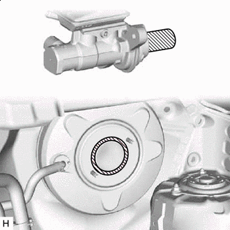

Apply Grease Apply a light layer of a grease enclosed with a new brake master cylinder sub-assembly or lithium soap base glycol grease to the circumference of the brake master cylinder sub-assembly and inner surface of the brake booster assembly as shown in the illustration.
-
Install the brake master cylinder sub-assembly to the brake booster assembly with the 2 nuts.
- Torque:
- 12.7 N*m { 130 kgf*cm, 9 ft.*lbf }
Note
-
The brake master cylinder sub-assembly requires careful handling. Do not drop or subject the brake master cylinder sub-assembly to any impact. Do not reuse a brake master cylinder sub-assembly that has been dropped.
-
Do not hold the brake master cylinder sub-assembly by the master cylinder piston. Hold the brake master cylinder sub-assembly by its body or its reservoir when carrying it.
-
Do not pull out the master cylinder piston.
-
Do not strike or pinch the master cylinder piston, or cause any damage to the master cylinder piston by any other means.
-
When installing the brake master cylinder sub-assembly to the brake booster assembly, or when removing the brake master cylinder sub-assembly from the brake booster assembly, make sure that the brake master cylinder sub-assembly is kept horizontal or with its tip facing downward (the master cylinder piston is facing upward) to prevent the master cylinder piston from falling out.
-
Do not allow any foreign matter to contaminate the master cylinder piston. If any foreign matter gets on the master cylinder piston, remove it by using a piece of cloth and then apply an even layer of lithium soap base glycol grease around the circumference (sliding part) of the master cylinder piston.
-
Do not kink or damage the brake lines.
-
Do not allow the brake lines to twist or interfere with other parts or the vehicle body during tightening.
-
Do not allow any foreign matter such as dirt or dust to enter the brake lines from the connecting parts.
-
Do not use any other type of grease or fluid.
-
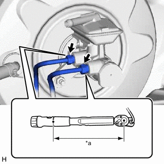
*a Torque Wrench Fulcrum Length Using a union nut wrench, connect the 2 brake lines to the brake master cylinder sub-assembly.
- Torque:
- Specified tightening torque
- 19.5 N*m { 199 kgf*cm, 14 ft.*lbf }
Note
-
Do not kink or damage the brake lines.
-
Do not allow any foreign matter such as dirt or dust to enter the brake lines from the connecting parts.
Tech Tips
-
Calculate the torque wrench reading when changing the fulcrum length of the torque wrench.
-
When using a union nut wrench (fulcrum length of 20 mm (0.787 in.)) + torque wrench (fulcrum length of 162 mm (6.38 in.)):
17.36 N*m (177 kgf*cm, 13 ft.*lbf)
-
-
CONNECT NO. 1 RESERVOIR TUBE
-
Connect the No. 1 reservoir tube to the brake master cylinder sub-assembly and slide the clip to secure it.
-
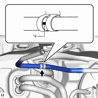
*a Paint Mark Install the No. 1 reservoir tube to the hose clamp bracket.
Note
Install the No. 1 reservoir tube so that the paint mark on the No. 1 reservoir tube is positioned as shown in the illustration.
-
-
INSTALL AIR CLEANER CASE SUB-ASSEMBLY
-
INSTALL AIR CLEANER CAP WITH AIR CLEANER HOSE
-
INSTALL V-BANK COVER SUB-ASSEMBLY
-
INSTALL BATTERY
-
INSTALL OUTER COWL TOP PANEL SUB-ASSEMBLY
-
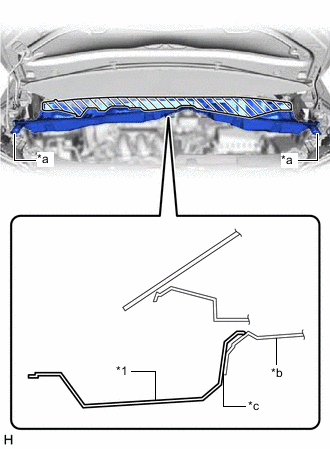
*1 Outer Cowl Top Panel Sub-assembly *a Outer Cowl Top Panel Sub-assembly Bracket *b Vehicle Body *c Align contact surfaces Install the outer cowl top panel sub-assembly to the vehicle body.
Note
-
Make sure to fully insert the outer cowl top panel sub-assembly so that the outer cowl top panel sub-assembly fully contacts the vehicle body in the shaded area shown in the illustration.
-
Check that there are no gaps between the contact surfaces of the outer cowl top panel sub-assembly bracket and vehicle body.
-
-
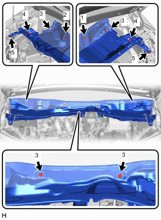
Install the 10 bolts in the order shown in the illustration.
- Torque:
- 12 N*m { 122 kgf*cm, 9 ft.*lbf }
Tech Tips
Tighten the bolts of the same number in any order.
-
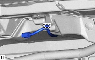
Engage the clamp to install the wire harness to the outer cowl top panel sub-assembly.
-
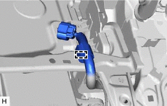
Engage the clamp to install the wire harness to the outer cowl top panel sub-assembly.
-
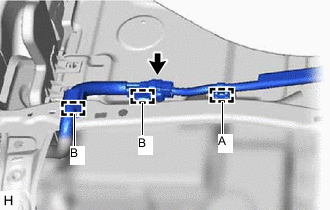
Engage the 2 clamps (B) to install the wire harness to the outer cowl top panel sub-assembly.
-
w/ Wiper Deicer System:
-
Engage the clamp (A) to install the wire harness to the outer cowl top panel sub-assembly.
-
Connect the connector.
-
-
-
INSTALL NO. 1 HEATER AIR DUCT SPLASH SHIELD SEAL
-
Engage the 2 claws to install the No. 1 heater air duct splash shield seal to the outer cowl top panel sub-assembly.
-
-
INSTALL NO. 2 HEATER AIR DUCT SPLASH SHIELD SEAL
-
Engage the 2 claws to install the No. 2 heater air duct splash shield seal to the outer cowl top panel sub-assembly.
-
-
INSTALL BRAKE MASTER CYLINDER RESERVOIR ASSEMBLY
-
Install the brake master cylinder reservoir assembly to the outer cowl top panel sub-assembly with the 2 bolts.
- Torque:
- 8.0 N*m { 82 kgf*cm, 71 in.*lbf }
-
Connect the connector to the brake master cylinder reservoir assembly.
-
-
INSTALL WINDSHIELD WIPER MOTOR AND LINK ASSEMBLY
-
INSPECT WASHER NOZZLE
-
CONNECT CABLE TO NEGATIVE BATTERY TERMINAL
Note
When disconnecting the cable, some systems need to be initialized after the cable is reconnected.
-
BLEED BRAKE SYSTEM