BRAKE MASTER CYLINDER(for LHD) REMOVAL
CAUTION / NOTICE / HINT
The necessary procedures (adjustment, calibration, initialization, or registration) that must be performed after parts are removed, installed, or replaced during the brake master cylinder sub-assembly removal/installation are shown below.
| Replacement Part or Procedure | Necessary Procedures | Effects/Inoperative when not Performed | Link |
|---|---|---|---|
| Disconnect cable from negative battery terminal | Drive the vehicle until stop and start control is permitted (approximately 5 to 60 minutes) | Stop and Start System | |
| Memorize steering angle neutral point | Panoramic View Monitor System | ||
| Initialize back door lock | Power Door Lock Control System | ||
| Initialize servo motor | Air Conditioning System | ||
| Reset slide door close position | Power Slide Door System | ||
| Reset back door close position | Power Back Door System |
CAUTION / NOTICE / HINT
Note
Make sure to release vacuum from the brake booster assembly before removing the brake master cylinder sub-assembly from the brake booster assembly.
PROCEDURE
-
PRECAUTION
Note
After turning the engine switch off, waiting time may be required before disconnecting the cable from the negative (-) battery terminal. Therefore, make sure to read the disconnecting the cable from the negative (-) battery terminal notices before proceeding with work.
-
DISCONNECT CABLE FROM NEGATIVE BATTERY TERMINAL
Note
When disconnecting the cable, some systems need to be initialized after the cable is reconnected.
-
REMOVE WINDSHIELD WIPER MOTOR AND LINK ASSEMBLY
-
SEPARATE BRAKE MASTER CYLINDER RESERVOIR ASSEMBLY
-
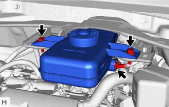
Disconnect the connector from the brake master cylinder reservoir assembly.
-
Remove the 2 bolts and separate the brake master cylinder reservoir assembly from the outer cowl top panel sub-assembly.
-
-
REMOVE NO. 1 HEATER AIR DUCT SPLASH SHIELD SEAL
-
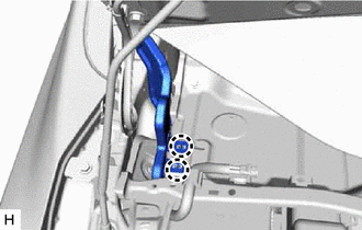
Disengage the 2 claws and remove the No. 1 heater air duct splash shield seal from the outer cowl top panel sub-assembly.
-
-
REMOVE NO. 2 HEATER AIR DUCT SPLASH SHIELD SEAL
-
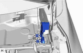
Disengage the 2 claws and remove the No. 2 heater air duct splash shield seal from the outer cowl top panel sub-assembly.
-
-
REMOVE OUTER COWL TOP PANEL SUB-ASSEMBLY
-
w/ Wiper Deicer System:
-
Disconnect the connector.
-
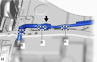
Disengage the clamp (A) and separate the wire harness from the outer cowl top panel sub-assembly.
-
-
Disengage the 2 clamps (B) and separate the wire harness from the outer cowl top panel sub-assembly.
-
Disengage the clamp and separate the wire harness from the outer cowl top panel sub-assembly.
-
Disengage the clamp and separate the wire harness from the outer cowl top panel sub-assembly.
-
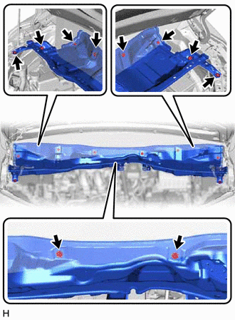
Remove the 10 bolts and outer cowl top panel sub-assembly.
-
-
REMOVE BATTERY
-
REMOVE V-BANK COVER SUB-ASSEMBLY
-
REMOVE AIR CLEANER CAP WITH AIR CLEANER HOSE
-
REMOVE AIR CLEANER CASE SUB-ASSEMBLY
-
DRAIN BRAKE FLUID
Note
If brake fluid leaks onto any painted surface, immediately wash it off.
-
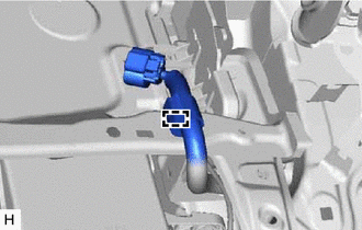
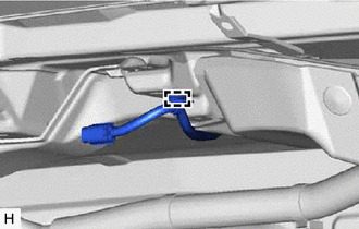
DISCONNECT NO. 1 RESERVOIR TUBE
-
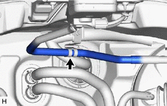
Separate the No. 1 reservoir tube from the hose clamp bracket.
-
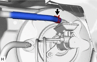
Slide the clip and disconnect the No. 1 reservoir tube from the brake master cylinder sub-assembly.
-
-
REMOVE BRAKE MASTER CYLINDER SUB-ASSEMBLY
-
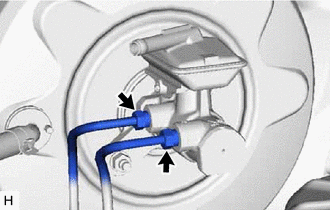
Using a union nut wrench, disconnect the 2 brake lines from the brake master cylinder sub-assembly.
Note
-
Do not damage or deform the brake lines.
-
Do not allow any foreign matter such as dirt or dust to enter the brake lines from the connecting parts.
-
-
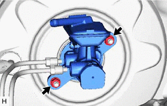
Remove the 2 nuts and brake master cylinder sub-assembly from the brake booster assembly.
Note
-
The brake master cylinder sub-assembly requires careful handling. Do not drop or subject the brake master cylinder sub-assembly to any impact. Do not reuse a brake master cylinder sub-assembly that has been dropped.
-
Do not hold the brake master cylinder sub-assembly by the master cylinder piston. Hold the brake master cylinder sub-assembly by its body or its reservoir when carrying it.
-
Do not pull out the master cylinder piston.
-
Do not strike or pinch the master cylinder piston, or cause any damage to the master cylinder piston by any other means.
-
When installing the brake master cylinder sub-assembly to the brake booster assembly, or when removing the brake master cylinder sub-assembly from the brake booster assembly, make sure that the brake master cylinder sub-assembly is kept horizontal or with its tip facing downward (the master cylinder piston is facing upward) to prevent the master cylinder piston from falling out.
-
Do not allow any foreign matter to contaminate the master cylinder piston. If any foreign matter gets on the master cylinder piston, remove it by using a piece of cloth and then apply an even layer of lithium soap base glycol grease around the circumference (sliding part) of the master cylinder piston.
-
Do not use any other type of grease or fluid.
-
Make sure to release vacuum from the brake booster assembly before removing the brake master cylinder sub-assembly from the brake booster assembly.
-
-
Remove the brake master cylinder O-ring from the brake master cylinder sub-assembly.
-