BRAKE PEDAL(for LHD) REMOVAL
CAUTION / NOTICE / HINT
The necessary procedures (adjustment, calibration, initialization, or registration) that must be performed after parts are removed, installed, or replaced during the brake pedal support assembly removal/installation are shown below.
| Replacement Part or Procedure | Necessary Procedures | Effects/Inoperative when not Performed | Link |
|---|---|---|---|
| Disconnect cable from negative battery terminal | Drive the vehicle until stop and start control is permitted (approximately 15 to 40 minutes) | Stop and start system | |
| Memorize steering angle neutral point | Panoramic view monitor system | ||
| Initialize back door lock | Power door lock control system | ||
| Initialize servo motor | Air Conditioning System | ||
| Reset slide door close position | Power slide door system | ||
| Reset back door close position | Power back door system |
CAUTION / NOTICE / HINT
Note
Make sure to release vacuum from the brake booster assembly before removing the brake master cylinder sub-assembly from the brake booster assembly.
PROCEDURE
-
REMOVE BRAKE MASTER CYLINDER SUB-ASSEMBLY
-
REMOVE LOWER NO. 1 INSTRUMENT PANEL AIRBAG ASSEMBLY
-
REMOVE STOP LIGHT SWITCH ASSEMBLY
-
REMOVE STOP LIGHT SWITCH MOUNTING ADJUSTER
-
SEPARATE JUNCTION BLOCK ASSEMBLY LH WITH MAIN BODY ECU
-
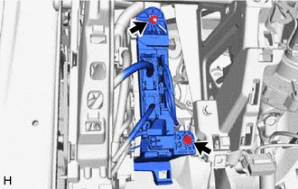
Remove the bolt and nut to separate the junction block assembly LH with main body ECU.
Note
Do not apply excessive force to the wire harnesses.
-
-
REMOVE BRAKE PEDAL RETURN SPRING
-
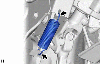
Remove the brake pedal return spring from the brake pedal support assembly.
-
-
REMOVE PUSH ROD PIN
-
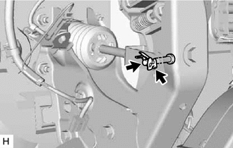
Remove the clip and push rod pin.
-
-
REMOVE BRAKE PEDAL SUPPORT ASSEMBLY
-
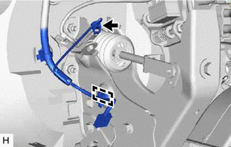
Disengage the clamp and disconnect the connector from the brake pedal support assembly.
-
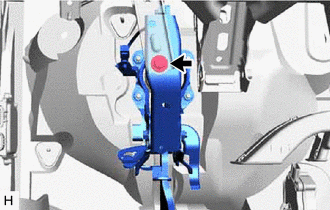
Remove the bolt and separate the brake pedal support assembly from the instrument panel reinforcement assembly.
-
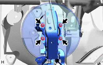
Remove the 4 nuts and push the brake booster assembly toward the engine compartment.
Note
-
Do not apply excessive force to the brake lines.
-
Do not drop the brake booster assembly.
-
-
Remove the brake pedal support assembly while avoiding the stud bolts of the brake booster assembly.
-
-
REMOVE BRAKE PEDAL PAD