CAN COMMUNICATION SYSTEM(for LHD) TERMINALS OF ECU
Note
-
After turning the engine switch off, waiting time may be required before disconnecting the cable from the negative (-) battery terminal. Therefore, make sure to read the disconnecting the cable from the negative (-) battery terminal notices before proceeding with work.
-
Turn the engine switch off before measuring the resistances between CAN main bus lines and between CAN branch lines.
-
Turn the engine switch off before inspecting CAN bus lines for a short to ground.
-
Before measuring the resistance of the CAN bus, turn the engine switch off and leave the vehicle for 1 minute or more without operating the key or any switches, or opening or closing the doors. After that, disconnect the cable from the negative (-) battery terminal and leave the vehicle for 1 minute or more before measuring the resistance.
-
This section describes the standard values for all CAN related components.
Tech Tips
-
Operating the engine switch, any other switches or a door triggers related ECU and sensor communication on the CAN. This communication will cause the resistance value to change.
-
Even after DTCs are cleared, if a DTC is stored again after driving the vehicle for a while, the malfunction may be occurring due to vibration of the vehicle. In such a case, wiggling the ECUs or wire harness while performing the inspection below may help determine the cause of the malfunction.
-
NO. 1 CAN JUNCTION CONNECTOR
-
Check the No. 1 CAN junction connector.
Tech Tips
Connectors that connect to the CAN junction connector can be distinguished by the color of their CAN bus lines. When the connectors have been disconnected from the CAN junction connector, reconnecting the connectors to non-original positions on the CAN junction connector does not affect system performance. However, it is preferred to reconnect the connectors to their original positions to avoid negative effects on the wiring such as tension on the wire harnesses, and to make future maintenance easier.
-
Connection diagram
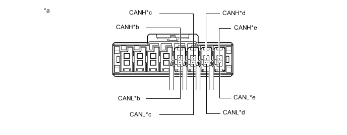
*a Component with harness connected
(No. 1 CAN Junction Connector)
*b to Outer Mirror Control ECU Assembly (for Front Passenger Side) *c to Slide Door Motor Unit RH *d to No. 5 CAN Junction Connector *e to Headlight Light Control ECU Sub-assembly LH - - -
Check the connection diagram of the components which are connected to the No. 1 CAN junction connector.
Terminal No. (Symbol) Wiring Color Connected to G86-1 (CANH) SB Outer mirror control ECU assembly (for front passenger side)
(for sub bus 1)
G86-2 (CANL) W G85-1 (CANH) LG Slide door motor unit RH
(for sub bus 1)
G85-2 (CANL) W G84-1 (CANH) BE No. 5 CAN junction connector
(for sub bus 1)
G84-2 (CANL) W G83-1 (CANH) B Headlight light control ECU sub-assembly LH
(for sub bus 1)
G83-2 (CANL) W
-
-
-
NO. 2 CAN JUNCTION CONNECTOR
-
Check the No. 2 CAN junction connector.
Tech Tips
Connectors that connect to the CAN junction connector can be distinguished by the color of their CAN bus lines. When the connectors have been disconnected from the CAN junction connector, reconnecting the connectors to non-original positions on the CAN junction connector does not affect system performance. However, it is preferred to reconnect the connectors to their original positions to avoid negative effects on the wiring such as tension on the wiring harnesses, and to make future maintenance easier.
-
Connection diagram
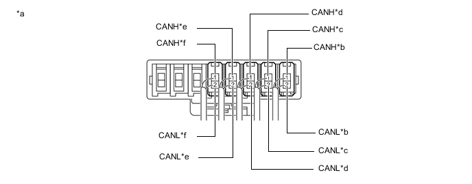
*a Component with harness connected
(No. 2 CAN Junction Connector)
*b to No. 2 CAN Junction Terminal *c to Network Gateway ECU *d to Parking Assist ECU
(w/ Panoramic View Monitor System)
*e to Inner Rear View Mirror Assembly
(w/ Automatic High Beam System)
*f to Telematics Transceiver
(w/ Manual (SOS) Switch)
-
Check the connection diagram of the components which are connected to the No. 2 CAN junction connector.
Terminal No. (Symbol) Wiring Color Connected to G88-1 (CANH) V No. 2 CAN junction terminal
(for sub bus 2)
G88-2 (CANL) W G89-1 (CANH) BE Network gateway ECU
(for sub bus 2)
G89-2 (CANL) W G92-1 (CANH) Y Parking assist ECU*1
(for sub bus 2)
G92-2 (CANL) W G93-1 (CANH) R Inner rear view mirror assembly*2
(for sub bus 2)
G93-2 (CANL) W G95-1 (CANH) LG Telematics transceiver*3
(for sub bus 2)
G95-2 (CANL) W
-
*1: w/ Panoramic View Monitor System
-
*2: w/ Automatic High Beam System
-
*3: w/ Manual (SOS) Switch
-
-
-
-
NO. 3 CAN JUNCTION CONNECTOR
-
Check the No. 3 CAN junction connector.
-
Connection diagram
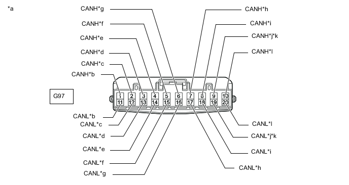
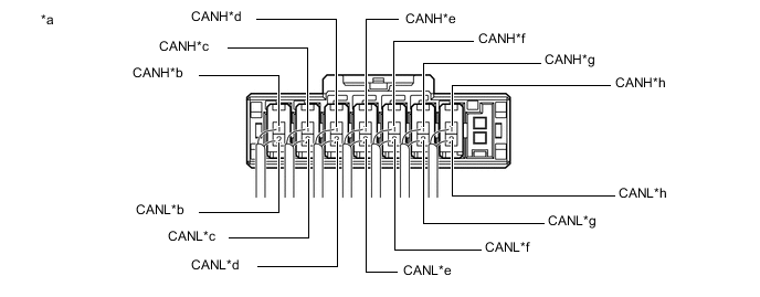
*a Front view of wire harness connector
(to No. 3 CAN Junction Connector)
*b to DLC3 *c to Steering Sensor *d to ECM *e to Main Body ECU (Multiplex Network Body ECU) *f to Airbag ECU Assembly *g to Parking Brake ECU Assembly *h to Skid Control ECU (Brake Actuator Assembly) *i to No. 4 CAN Junction Connector *j to Navigation Receiver Assembly
(for Navigation Receiver Type)
*k to Radio and Display Receiver Assembly
(for Radio and Display Type)
*l to Power Steering ECU Assembly -
Check the connection diagram of the components which are connected to the No. 3 CAN junction connector.
Terminal No. (Symbol) Wiring Color Connected to G97-1 (CANH) V DLC3
(for V bus)
G97-11 (CANL) W G97-2 (CANH) BE Steering sensor
(for V bus)
G97-12 (CANL) W G97-3 (CANH) LG ECM
(for V bus)
G97-13 (CANL) W G97-4 (CANH) R Main body ECU (multiplex network body ECU)
(for V bus)
G97-14 (CANL) W G97-5 (CANH) Y Airbag ECU assembly
(for V bus)
G97-15 (CANL) W G97-6 (CANH) G Parking brake ECU assembly
(for V bus)
G97-16 (CANL) W G97-7 (CANH) GR Skid control ECU (brake actuator assembly)
(for V bus)
G97-17 (CANL) W G97-8 (CANH) B No. 4 CAN junction connector
(for V bus)
G97-18 (CANL) W G97-9 (CANH) L Navigation receiver assembly*1
(for V bus)
G97-19 (CANL) W G97-9 (CANH) L Radio and display receiver assembly*2
(for V bus)
G97-19 (CANL) W G97-10 (CANH) P Power steering ECU assembly
(for V bus)
G97-20 (CANL) W
-
*1: for Navigation Receiver Type
-
*2: for Radio and Display Type
-
-
-
-
NO. 4 CAN JUNCTION CONNECTOR
-
Check the No. 4 CAN junction connector.
-
Connection diagram
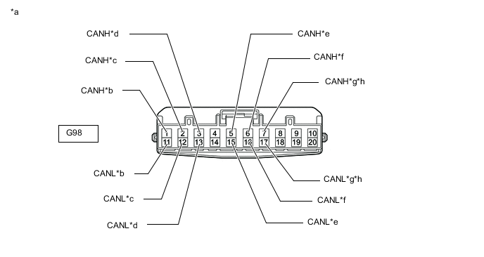
*a Front view of wire harness connector
(to No. 4 CAN Junction Connector)
*b to No. 3 CAN Junction Connector *c to Combination Meter Assembly *d to Certification ECU (Smart Key ECU Assembly) *e to Air Conditioning Amplifier Assembly *f to Clearance Warning ECU Assembly *g to Network Gateway ECU
(w/ Network Gateway ECU)
*h to Option Connector (Bus Buffer ECU)
(w/o Network Gateway ECU)
-
Check the connection diagram of the components which are connected to the No. 4 CAN junction connector.
Terminal No. (Symbol) Wiring Color Connected to G98-1 (CANH) B No. 3 CAN junction connector
(for V bus)
G98-11 (CANL) W G98-2 (CANH) Y Combination meter assembly
(for V bus)
G98-12 (CANL) W G98-3 (CANH) G Certification ECU (smart key ECU assembly)
(for V bus)
G98-13 (CANL) W G98-5 (CANH) BE Air conditioning amplifier assembly
(for V bus)
G98-15 (CANL) W G98-6 (CANH) LG Clearance warning ECU assembly
(for V bus)
G98-16 (CANL) W G98-7 (CANH) P Network gateway ECU*1
(for V bus)
G98-17 (CANL) W G98-7 (CANH) P Option connector (bus buffer ECU)*2
(for V bus)
G98-17 (CANL) W
-
*1: w/ Network Gateway ECU
-
*2: w/o Network Gateway ECU
-
-
-
-
NO. 5 CAN JUNCTION CONNECTOR
-
Check the No. 5 CAN junction connector.
Tech Tips
Connectors that connect to the CAN junction connector can be distinguished by the color of their CAN bus lines. When the connectors have been disconnected from the CAN junction connector, reconnecting the connectors to non-original positions on the CAN junction connector does not affect system performance. However, it is preferred to reconnect the connectors to their original positions to avoid negative effects on the wiring such as tension on the wire harnesses, and to make future maintenance easier.
-
Connection diagram
*a Component with harness connected
(No. 5 CAN Junction Connector)
*b to Main Body ECU (Multiplex Network Body ECU) *c to No. 1 CAN Junction Connector *d to Room Light Control Relay *e to Slide Door Motor Unit LH *f to Back Door Motor Unit *g to Outer Mirror Control ECU Assembly (for Driver Side) *h to Front Power Seat Switch LH -
Check the connection diagram of the components which are connected to the No. 5 CAN junction connector.
Terminal No. (Symbol) Wiring Color Connected to G99-1 (CANH) G Main body ECU (multiplex network body ECU)
(for sub bus 1)
G99-2 (CANL) W G100-1 (CANH) BE No. 1 CAN junction connector
(for sub bus 1)
G100-2 (CANL) W G101-1 (CANH) V Room light control relay
(for sub bus 1)
G101-2 (CANL) W G102-1 (CANH) P Slide door motor unit LH
(for sub bus 1)
G102-2 (CANL) W G103-1 (CANH) L Back door motor unit
(for sub bus 1)
G103-2 (CANL) W G104-1 (CANH) SB Outer mirror control ECU assembly (for driver side)
(for sub bus 1)
G104-2 (CANL) W G105-1 (CANH) GR Front power seat switch LH
(for sub bus 1)
G105-2 (CANL) W
-
-
-
NO. 2 CAN JUNCTION TERMINAL
-
Check the No. 2 CAN junction terminal.
-
Connection diagram

*a Front view of wire harness connector
(to No. 2 CAN Junction Terminal)
*b to No. 2 CAN Junction Connector -
Check the connection diagram of the components which are connected to the No. 2 CAN junction terminal.
Terminal No. (Symbol) Wiring Color Connected to G96-3 (CANH) V No. 2 CAN junction connector
(for sub bus 2)
G96-2 (CANL) W
-
-
-
DLC3
-
Disconnect the cable from the negative (-) battery terminal.
-
Measure the resistance according to the value(s) in the table below.
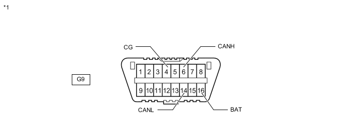
*1 DLC3 - -
-
-
ECM
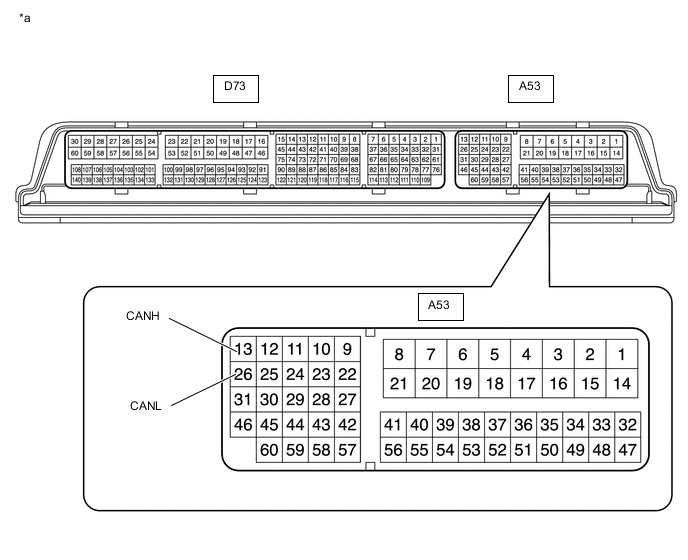
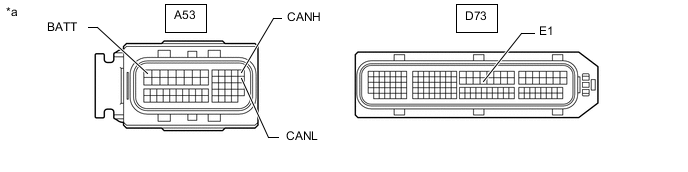
*a Component without harness connected
(ECM)
- -
-
Disconnect the cable from the negative (-) battery terminal.
-
Disconnect the A53 and D73 ECM connectors.
-
Measure the resistance according to the value(s) in the table below.
*a Front view of wire harness connector
(to ECM)
- -
-
-
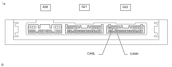
CERTIFICATION ECU (SMART KEY ECU ASSEMBLY)
*a Component without harness connected
(Certification ECU (Smart Key ECU Assembly))
- -
-
Disconnect the cable from the negative (-) battery terminal.
-
Disconnect the G22 certification ECU (smart key ECU assembly) connector.
-
Measure the resistance according to the value(s) in the table below.

*a Front view of wire harness connector
(to Certification ECU (Smart Key ECU Assembly))
- -
-
-
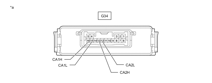
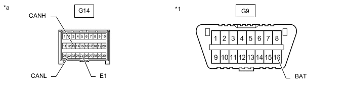
NETWORK GATEWAY ECU (w/ Network Gateway ECU)
*a Component without harness connected
(Network Gateway ECU)
- -
-
Disconnect the cable from the negative (-) battery terminal.
-
Disconnect the G34 network gateway ECU connector.
-
Measure the resistance according to the value(s) in the table below.

*a Front view of wire harness connector
(to Network Gateway ECU)
- -
-
-
JUNCTION BLOCK ASSEMBLY LH AND MAIN BODY ECU (MULTIPLEX NETWORK BODY ECU)
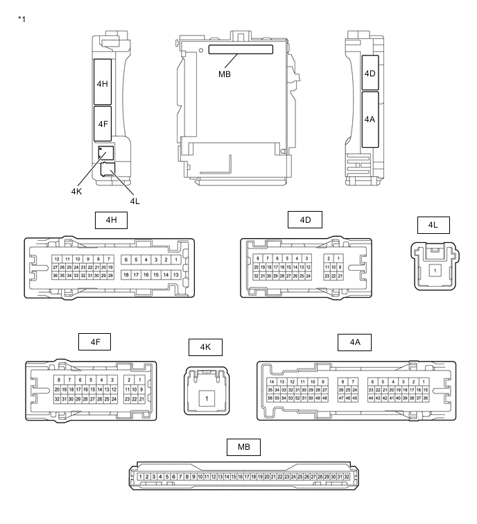
*1 Junction Block Assembly LH - - 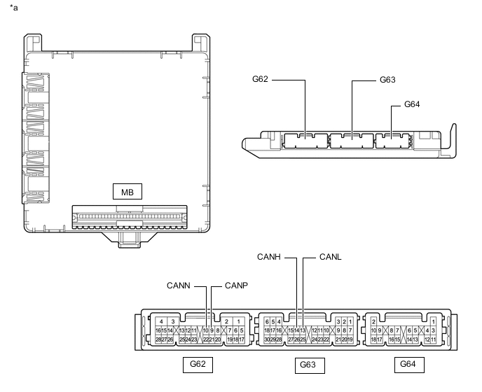
*a Component without harness connected
(Main Body ECU (Multiplex Network Body ECU))
- -
-
Disconnect the cable from the negative (-) battery terminal.
-
Disconnect the G62 and G63 main body ECU (multiplex network body ECU) connectors.
-
Measure the resistance according to the value(s) in the table below.
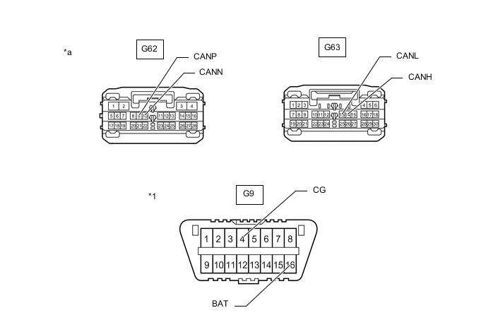
*1 DLC3 - - *a Front view of wire harness connector
(to Main Body ECU (Multiplex Network Body ECU))
- -
-
-
POWER STEERING ECU ASSEMBLY
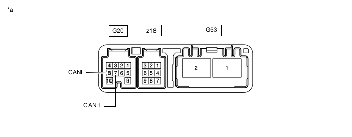
*a Component without harness connected
(Power Steering ECU Assembly)
- -
-
Disconnect the cable from the negative (-) battery terminal.
-
Disconnect the G20 and G53 power steering ECU assembly connectors.
-
Measure the resistance according to the value(s) in the table below.
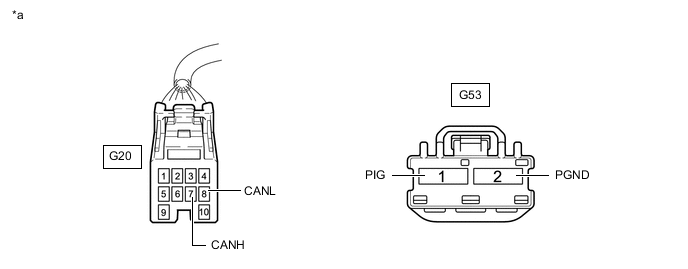
*a Front view of wire harness connector
(to Power Steering ECU Assembly)
- -
-
-
SKID CONTROL ECU (BRAKE ACTUATOR ASSEMBLY)
-
Disconnect the cable from the negative (-) battery terminal.
-
Disconnect the A50 skid control ECU (brake actuator assembly) connector.
-
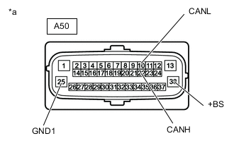
*a Front view of wire harness connector
(to Skid Control ECU (Brake Actuator Assembly))
Measure the resistance according to the value(s) in the table below.
-
-
AIRBAG ECU ASSEMBLY
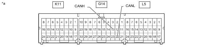
*a Component without harness connected
(Airbag ECU Assembly)
- -
-
Disconnect the cable from the negative (-) battery terminal.
-
Disconnect the G14 airbag ECU assembly connector.
-
Measure the resistance according to the value(s) in the table below.
*1 DLC3 - - *a Front view of wire harness connector
(to Airbag ECU Assembly)
- -
-
-
STEERING SENSOR
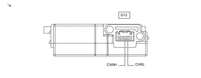
*a Component without harness connected
(Steering Sensor)
- -
-
Disconnect the cable from the negative (-) battery terminal.
-
Disconnect the G12 steering sensor connector.

*a Front view of wire harness connector
(to Steering Sensor)
- - -
Measure the resistance according to the value(s) in the table below.
-
-
AIR CONDITIONING AMPLIFIER ASSEMBLY
-
Disconnect the cable from the negative (-) battery terminal.
-
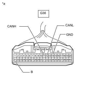
*a Front view of wire harness connector
(to Air Conditioning Amplifier Assembly)
Disconnect the G36 air conditioning amplifier assembly connector.
-
Measure the resistance according to the value(s) in the table below.
-
-
COMBINATION METER ASSEMBLY
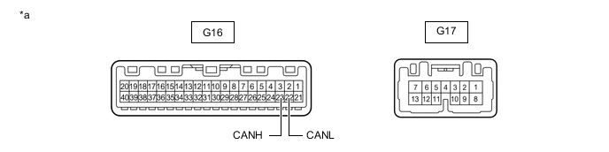
*a Component without harness connected
(Combination Meter Assembly)
- -
-
Disconnect the cable from the negative (-) battery terminal.
-
Disconnect the G16 combination meter assembly connector.
-
Measure the resistance according to the value(s) in the table below.

*a Front view of wire harness connector
(to Combination Meter Assembly)
- -
-
-
CLEARANCE WARNING ECU ASSEMBLY
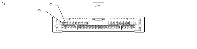
*a Component without harness connected
(Clearance Warning ECU Assembly)
- -
-
Disconnect the cable from the negative (-) battery terminal.
-
Disconnect the G59 clearance warning ECU assembly connector.
-
Measure the resistance according to the value(s) in the table below.
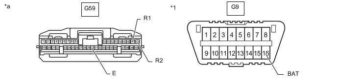
*1 DLC3 - - *a Front view of wire harness connector
(to Clearance Warning ECU Assembly)
- -
-
-
PARKING BRAKE ECU ASSEMBLY
-
Disconnect the cable from the negative (-) battery terminal.
-
Disconnect the K14 and K15 parking brake ECU assembly connectors.
-
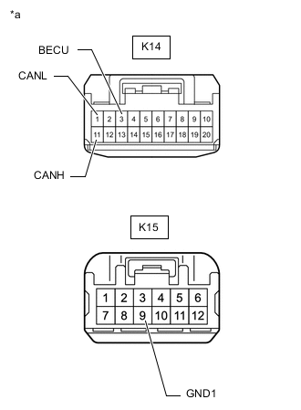
*a Front view of wire harness connector
(to Parking Brake ECU Assembly)
Measure the resistance according to the value(s) in the table below.
-
-
OPTION CONNECTOR (BUS BUFFER ECU) (w/o Network Gateway ECU)
-
Disconnect the cable from the negative (-) battery terminal.
-
Measure the resistance according to the value(s) in the table below.
*1 DLC3 - - *a Front view of wire harness connector
(to Option Connector (Bus Buffer ECU))
- -
-
-
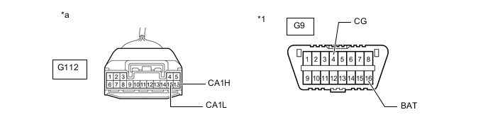
NAVIGATION RECEIVER ASSEMBLY (for Navigation Receiver Type with Panoramic View Monitor System)
-
Disconnect the cable from the negative (-) battery terminal.
-
Disconnect the F1 and F3 navigation receiver assembly connectors.
-

*a Front view of wire harness connector
(to Navigation Receiver Assembly)
Measure the resistance according to the value(s) in the table below.
-
-
NAVIGATION RECEIVER ASSEMBLY (for Navigation Receiver Type without Panoramic View Monitor System)
-
Disconnect the cable from the negative (-) battery terminal.
-
Disconnect the F1 and F3 navigation receiver assembly connectors.
-
*a Front view of wire harness connector
(to Navigation Receiver Assembly)
Measure the resistance according to the value(s) in the table below.
-
-
RADIO AND DISPLAY RECEIVER ASSEMBLY (for Radio and Display Type with Navigation System)
-
Disconnect the cable from the negative (-) battery terminal.
-
Disconnect the F37 and F39 radio and display receiver assembly connectors.
-
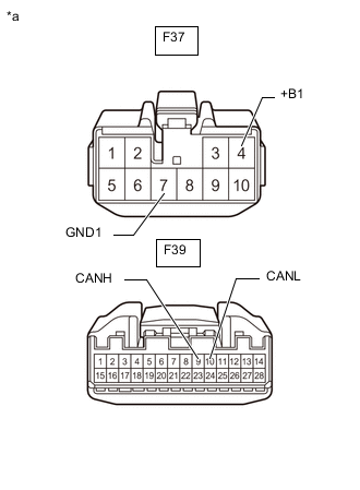
*a Front view of wire harness connector
(to Radio and Display Receiver Assembly)
Measure the resistance according to the value(s) in the table below.
-
-
RADIO AND DISPLAY RECEIVER ASSEMBLY (for Radio and Display Type without Navigation System)
-
Disconnect the cable from the negative (-) battery terminal.
-
Disconnect the F37 and F39 radio and display receiver assembly connectors.
-
*a Front view of wire harness connector
(to Radio and Display Receiver Assembly)
Measure the resistance according to the value(s) in the table below.
-
-
HEADLIGHT LIGHT CONTROL ECU SUB-ASSEMBLY LH
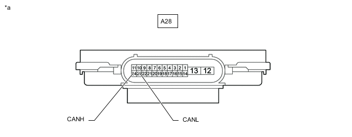
*a Component without harness connected
(Headlight Light Control ECU Sub-assembly LH)
- -
-
Disconnect the cable from the negative (-) battery terminal.
-
Disconnect the A28 headlight light control ECU sub-assembly LH connector.
-
Measure the resistance according to the value(s) in the table below.
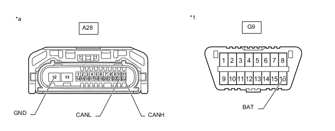
*1 DLC3 - - *a Front view of wire harness connector
(to Headlight Light Control ECU Sub-assembly LH)
- -
-
-
OUTER MIRROR CONTROL ECU ASSEMBLY (for Driver Side)

*a Component without harness connected
(Outer Mirror Control ECU Assembly (for Driver Side))
- -
-
Disconnect the cable from the negative (-) battery terminal.
-
Disconnect the I28 outer mirror control ECU assembly (for driver side) connector.
-
Measure the resistance according to the value(s) in the table below.

*a Front view of wire harness connector
(Outer Mirror Control ECU Assembly (for Driver Side))
- -
-
-
OUTER MIRROR CONTROL ECU ASSEMBLY (for Front Passenger Side)

*a Component without harness connected
(Outer Mirror Control ECU Assembly (for Front Passenger Side))
- -
-
Disconnect the cable from the negative (-) battery terminal.
-
Disconnect the I13 outer mirror control ECU assembly (for front passenger side) connector.

*a Front view of wire harness connector
(to Outer Mirror Control ECU Assembly (for Front Passenger Side))
- - -
Measure the resistance according to the value(s) in the table below.
-
-
FRONT POWER SEAT SWITCH LH

*a Component without harness connected
(Front Power Seat Switch LH)
- -
-
Disconnect the cable from the negative (-) battery terminal.
-
Disconnect the W19 and W20 front power seat switch LH connectors.
-
Measure the resistance according to the value(s) in the table below.
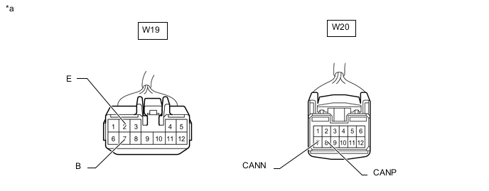
*a Front view of wire harness connector
(to Front Power Seat Switch LH)
- -
-
-
BACK DOOR MOTOR UNIT
-
Disconnect the cable from the negative (-) battery terminal.
-
Disconnect the K22 back door motor unit connector.
-
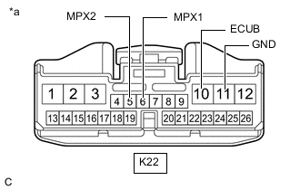
*a Front view of wire harness connector
(to Back Door Motor Unit)
Measure the resistance according to the value(s) in the table below.
-
-
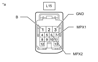
SLIDE DOOR MOTOR UNIT LH
-
Disconnect the cable from the negative (-) battery terminal.
-
Disconnect the K19 slide door motor unit LH connector.
-

*a Front view of wire harness connector
(to Slide Door Motor Unit LH)
Measure the resistance according to the value(s) in the table below.
-
-
SLIDE DOOR MOTOR UNIT RH
-
Disconnect the cable from the negative (-) battery terminal.
-
Disconnect the L15 slide door motor unit RH connector.
-
*a Front view of wire harness connector
(to Slide Door Motor Unit RH)
Measure the resistance according to the value(s) in the table below.
-
-
ROOM LIGHT CONTROL RELAY
-
Disconnect the cable from the negative (-) battery terminal.
-
Disconnect the S30 room light control relay connector.
-
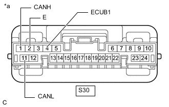
*a Front view of wire harness connector
(to Room Light Control Relay)
Measure the resistance according to the value(s) in the table below.
-
-
INNER REAR VIEW MIRROR ASSEMBLY (w/ Automatic High Beam System)
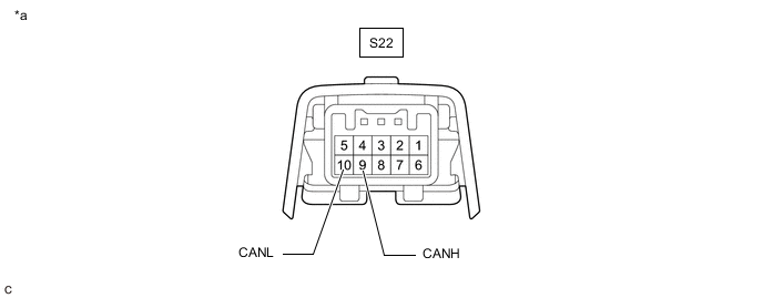
*a Component without harness connected
(Inner Rear View Mirror Assembly)
- -
-
Disconnect the cable from the negative (-) battery terminal.
-
Disconnect the S22 inner rear view mirror assembly connector.
-
Measure the resistance according to the value(s) in the table below.
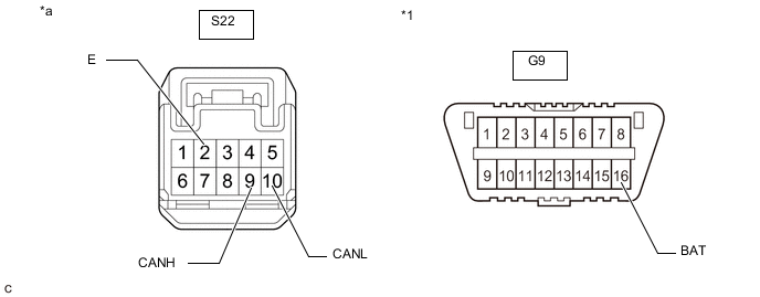
*1 DLC3 - - *a Front view of wire harness connector
(to Inner Rear View Mirror Assembly)
- -
-
-
PARKING ASSIST ECU (w/ Panoramic View Monitor System)
-
Disconnect the cable from the negative (-) battery terminal.
-
Disconnect the F9 parking assist ECU connector.
-
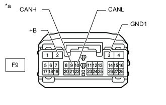
*a Front view of wire harness connector
(to Parking Assist ECU)
Measure the resistance according to the value(s) in the table below.
-
-
TELEMATICS TRANSCEIVER (w/ Manual (SOS) Switch)
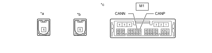
*a Connector Color: Gray (to GNSS Antenna) *b Connector Color: Blue (to Telephone Antenna) *c Component without harness connected
(Telematics Transceiver)
- -
-
Disconnect the cable from the negative (-) battery terminal.
-
Disconnect the M1 telematics transceiver connector.
-
Measure the resistance according to the value(s) in the table below.

*a Front view of wire harness connector
(to Telematics Transceiver)
- -
-