CAN COMMUNICATION SYSTEM(for LHD) SYSTEM DIAGRAM
-
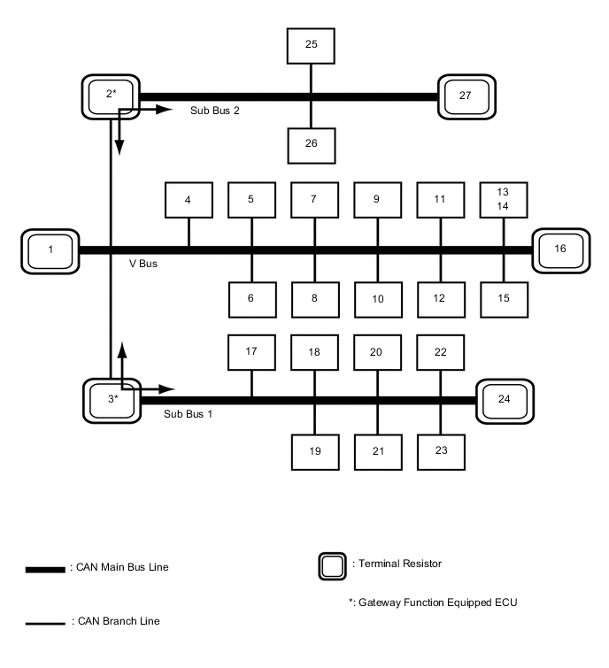
OVERALL CAN BUS DIAGRAM
-
The CAN communication system is composed of 3 buses.
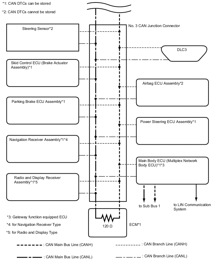
1 ECM
(for V Bus)
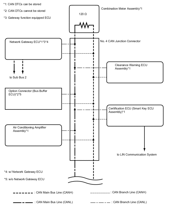
2 Network Gateway ECU
(w/ Network Gateway ECU)
(for V Bus and Sub Bus 2)
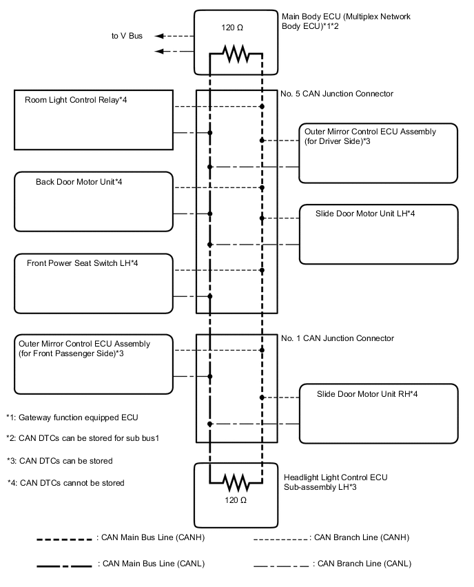
3 Main Body ECU (Multiplex Network Body ECU)
(for V Bus and Sub Bus 1)
4 Option Connector (Bus Buffer ECU)
(w/o Network Gateway ECU)
(for V Bus)
5 Power Steering ECU Assembly
(for V Bus)
6 Air Conditioning Amplifier Assembly
(for V Bus)
7 Airbag ECU Assembly
(for V Bus)
8 Parking Brake ECU Assembly
(for V Bus)
9 Certification ECU (Smart Key ECU Assembly)
(for V Bus)
10 DLC3
(for V Bus)
11 Steering Sensor
(for V Bus)
12 Skid Control ECU (Brake Actuator Assembly)
(for V Bus)
13 Radio and Display Receiver Assembly
(for Radio and Display Type)
(for V Bus)
14 Navigation Receiver Assembly
(for Navigation Receiver Type)
(for V Bus)
15 Clearance Warning ECU Assembly
(for V Bus)
16 Combination Meter Assembly
(for V Bus)
17 Room Light Control Relay
(for Sub Bus 1)
18 Outer Mirror Control ECU Assembly (for Driver Side)
(for Sub Bus 1)
19 Outer Mirror Control ECU Assembly (for Front Passenger Side)
(for Sub Bus 1)
20 Front Power Seat Switch LH
(for Sub Bus 1)
21 Back Door Motor Unit
(for Sub Bus 1)
22 Slide Door Motor Unit LH
(for Sub Bus 1)
23 Slide Door Motor Unit RH
(for Sub Bus 1)
24 Headlight Light Control ECU Sub-assembly LH
(for Sub Bus 1)
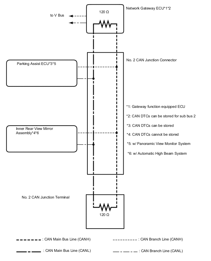
25 Inner Rear View Mirror Assembly
(w/ Automatic High Beam System)
(for Sub Bus 2)
26 Parking Assist ECU
(w/ Panoramic View Monitor System)
(for Sub Bus 2)
27 No. 2 CAN Junction Terminal
(for Sub Bus 2)
- - Tech Tips
-
The main body ECU (multiplex network body ECU) functions as a gateway between the V bus and sub bus 1.
-
The network gateway ECU functions as a gateway between the V bus and sub bus 2.
-
Refer to the following bus wiring diagrams for details.
-
-
-
V BUS
Tech Tips
The CAN communication system connects to other networks via ECUs that function as a gateway.
-
SUB BUS 1
-
SUB BUS 2 (w/ Network Gateway ECU)