INTEGRATION RELAY REMOVAL
CAUTION / NOTICE / HINT
The necessary procedures (adjustment, calibration, initialization, or registration) that must be performed after parts are removed, installed, or replaced during the No. 1 integration relay removal/installation are shown below.
| Replacement part or procedure | Necessary procedures | Effects/Inoperative when not performed | Link |
|---|---|---|---|
| Disconnect cable from negative battery terminal | Drive the vehicle until stop and start control is permitted (approximately 5 to 60 minutes) | Stop and Start System (for 2AR-FE) | |
| Stop and Start System (for 2GR-FKS) | |||
| Memorize steering angle neutral point | Panoramic view monitor system | ||
| Initialize back door lock | Power door lock control system | ||
| Initialize servo motor | Air Conditioning System | ||
| Reset slide door close position | Power slide door system | ||
| Reset back door close position | Power back door system |
PROCEDURE
-
PRECAUTION
Note
After turning the engine switch off, waiting time may be required before disconnecting the cable from the negative (-) battery terminal. Therefore, make sure to read the disconnecting the cable from the negative (-) battery terminal notices before proceeding with work.
-
DISCONNECT CABLE FROM NEGATIVE BATTERY TERMINAL
Note
When disconnecting the cable, some systems need to be initialized after the cable is reconnected.
-
REMOVE NO. 2 RELAY BLOCK COVER
-
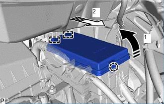

Remove in this Direction (1) 
Remove in this Direction (2) Disengage the 2 guides and claw to remove the No. 2 relay block cover as indicated by the arrows, in the order shown in the illustration.
-
-
REMOVE NO. 1 INTEGRATION RELAY
-
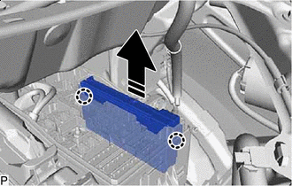
Remove in this Direction Disengage the 2 claws.
-
Pull up the No. 1 integration relay as shown in the illustration.
Note
When pulling the No. 1 integration relay, take care not to damage it.
-
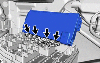
Disconnect the 4 connectors and remove the No. 1 integration relay.
Note
When pulling the No. 1 integration relay, take care not to damage it.
-