MAIN BODY ECU REMOVAL
CAUTION / NOTICE / HINT
The necessary procedures (adjustment, calibration, initialization, or registration) that must be performed after parts are removed, installed, or replaced during the main body ECU (multiplex network body ECU) removal/installation are shown below.
| Replacement part or procedure | Necessary procedures | Effects/Inoperative when not performed | Link |
|---|---|---|---|
| Disconnect cable from negative battery terminal | Drive the vehicle until stop and start control is permitted (approximately 5 to 60 minutes) | Stop and Start System (for 2AR-FE) | |
| Stop and Start System (for 2GR-FKS) | |||
| Memorize steering angle neutral point | Panoramic view monitor system | ||
| Initialize back door lock | Power door lock control system | ||
| Initialize servo motor | Air Conditioning System | ||
| Reset slide door close position | Power slide door system | ||
| Reset back door close position | Power back door system | ||
| Replacement of main body ECU (multiplex network body ECU) | Perform code registration (Immobiliser system) |
|
See Service Bulletin for the registration method. |
| Turning the engine switch on (IG) | Automatic light control system |
PROCEDURE
-
PRECAUTION (for RHD)
Note
After turning the engine switch off, waiting time may be required before disconnecting the cable from the negative (-) battery terminal. Therefore, make sure to read the disconnecting the cable from the negative (-) battery terminal notices before proceeding with work.
-
DISCONNECT CABLE FROM NEGATIVE BATTERY TERMINAL (for RHD)
Note
When disconnecting the cable, some systems need to be initialized after the cable is reconnected.
-
REMOVE LOWER NO. 1 INSTRUMENT PANEL AIRBAG ASSEMBLY (for LHD)
-
REMOVE COWL SIDE TRIM BOARD LH (for LHD)
-
REMOVE LOWER INSTRUMENT PANEL FINISH PANEL ASSEMBLY (for LHD)
-
REMOVE CONSOLE BOX ASSEMBLY (for RHD)
for Integrated Console Box Type: Click here
-
REMOVE CENTER NO. 2 INSTRUMENT CLUSTER FINISH PANEL (for RHD)
for Separate Console Box Type: Click here
-
REMOVE CENTER NO. 1 INSTRUMENT CLUSTER FINISH PANEL (for RHD)
for Separate Console Box Type: Click here
-
REMOVE UPPER INSTRUMENT PANEL FINISH PANEL (for RHD)
-
REMOVE INSTRUMENT PANEL BOX ASSEMBLY (for RHD)
for Separate Console Box Type: Click here
-
REMOVE INSTRUMENT CLUSTER FINISH PANEL ASSEMBLY (for RHD)
for Separate Console Box Type: Click here
-
REMOVE GLOVE COMPARTMENT DOOR ASSEMBLY (for RHD)
-
REMOVE NO. 3 INSTRUMENT CLUSTER FINISH PANEL GARNISH (for RHD)
-
REMOVE COWL SIDE TRIM BOARD LH (for RHD)
-
REMOVE NO. 2 INSTRUMENT PANEL UNDER COVER SUB-ASSEMBLY (for RHD)
-
REMOVE LOWER NO. 2 INSTRUMENT PANEL FINISH PANEL (for RHD)
-
REMOVE LOWER INSTRUMENT PANEL (for RHD)
-
REMOVE JUNCTION BLOCK ASSEMBLY LH WITH MAIN BODY ECU (for LHD)
-
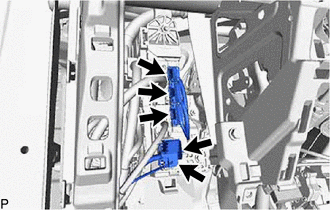
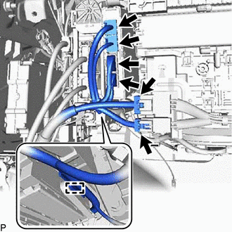
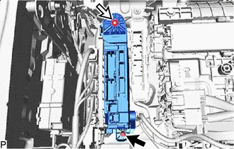
Disconnect each connector.
-

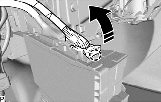
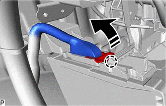
Remove in this Direction Disengage the claw and pull down the lock lever to disconnect the connector as shown in the illustration.
-
Remove in this Direction Disengage the claw and pull down the lock lever to disconnect the connector as shown in the illustration.
-

Bolt 
Nut Remove the bolt and nut.
-
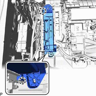
Disengage the clamp.
-
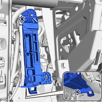
Disengage the 2 claws to disconnect the junction block assembly LH with main body ECU.
-
Pull out the junction block assembly LH with main body ECU.
-
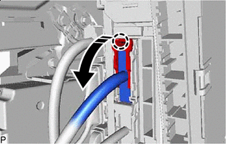
Remove in this Direction Disengage the claw and raise the lock lever to disconnect the connector as shown in the illustration.
-
w/ Connector Lock:
-
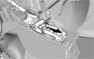
Remove in this Direction Disengage the claw and slide the connector lock as shown in the illustration.
-
-
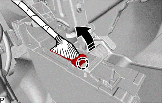
Remove in this Direction Disengage the claw and raise the lock lever to disconnect the connector as shown in the illustration and remove the junction block assembly LH with main body ECU.
-
-
REMOVE JUNCTION BLOCK ASSEMBLY LH WITH MAIN BODY ECU (for RHD)
-
Disconnect each connector.
-
Disengage the clamp.
-
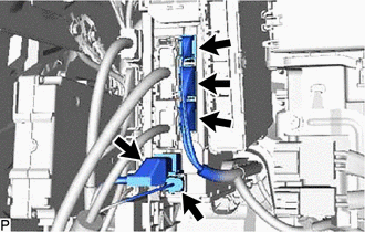
Disconnect each connector.
-
Remove in this Direction Disengage the claw and pull down the lock lever to disconnect the connector as shown in the illustration.
-
Remove in this Direction Disengage the claw and pull down the lock lever to disconnect the connector as shown in the illustration.
-
Bolt Nut Remove the bolt and nut.
-
Disengage the 2 claws to disconnect the junction block assembly LH with main body ECU.
-
Pull out the junction block assembly LH with main body ECU.
-
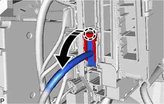
Remove in this Direction Disengage the claw and raise the lock lever to disconnect the connector as shown in the illustration.
-
w/ Connector Lock:
-
Remove in this Direction Disengage the claw and slide the connector lock as shown in the illustration.
-
-
Remove in this Direction Disengage the claw and raise the lock lever to disconnect the connector as shown in the illustration and remove the junction block assembly LH with main body ECU.
-
-
REMOVE MAIN BODY ECU (MULTIPLEX NETWORK BODY ECU)
-
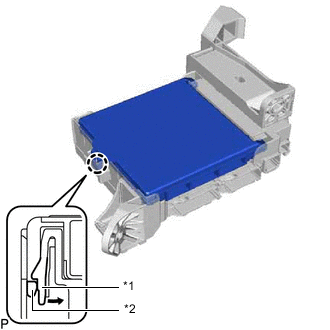
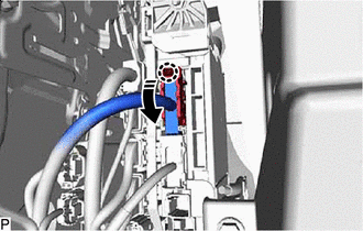
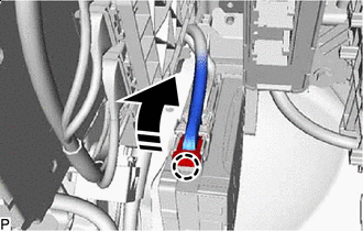
*1 Junction block assembly LH *2 Main Body ECU (Multiplex Network Body ECU) Push in this Direction Press the claw of the junction block assembly LH as shown in the illustration to release the lock.
-
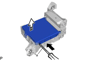
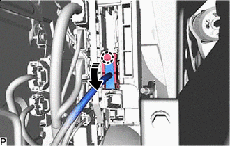
*a Protective Tape Insert in this Direction 
Remove in this Direction With the junction block assembly LH lock released, insert a screwdriver with its tip wrapped with protective tape horizontally between the main body ECU (multiplex network body ECU) and junction block assembly LH.
Note
-
Use a screwdriver with a diameter between 5.0 mm (0.197 in.) and 6.3 mm (0.248 in.) and a length of approximately 90 mm (3.54 in.).
-
Do not insert the screwdriver under the connector socket of the main body ECU (multiplex network body ECU).
-
-
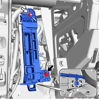
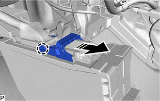
Using the screwdriver, carefully raise the main body ECU (multiplex network body ECU) to the position where the connector becomes disconnected.
Note
Do not twist the screwdriver to raise the main body ECU (multiplex network body ECU).
-
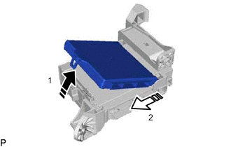
Remove in this Direction (1) Remove in this Direction (2) Raise the main body ECU (multiplex network body ECU) as shown by the arrow (1), and then pull it out as shown by the arrow (2) in the illustration.
Note
Do not touch the main body ECU (multiplex network body ECU) connector.
-