LIN COMMUNICATION SYSTEM TERMINALS OF ECU
-
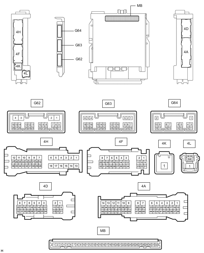
CHECK MAIN BODY ECU (MULTIPLEX NETWORK BODY ECU) AND JUNCTION BLOCK ASSEMBLY LH
-
Remove the main body ECU (multiplex network body ECU) from the junction block assembly LH.
-
Reconnect the junction block assembly LH connectors.
-
Measure the resistance and voltage according to the value(s) in the table below.
Tech Tips
Measure the values on the wire harness side with the connector disconnected.
Terminal No. (Symbol) Wiring Color Terminal Description Condition Specified Condition MB-11 (GND1) - Body ground - Ground Always Below 1 Ω MB-31 (BECU) - Body ground - Battery power supply Always 11 to 14 V MB-30 (ACC) - Body ground - ACC power supply Engine switch on (ACC) 11 to 14 V MB-30 (ACC) - Body ground - ACC power supply Engine switch off Below 1 V MB-32 (IG) - Body ground - IG power supply Engine switch on (IG) 11 to 14 V MB-32 (IG) - Body ground - IG power supply Engine switch off Below 1 V -
Install the main body ECU (multiplex network body ECU) to junction block assembly LH.
-
Check for pulses according to the value(s) in the table below.
Terminal No. (Symbol) Wiring Color Terminal Description Condition Specified Condition 4D-11 - Body ground LG - Body ground LIN communication line Engine switch on (IG) Pulse generation 4H-25 - Body ground P - Body ground LIN communication line Engine switch on (IG) Pulse generation 4H-26 - Body ground V - Body ground LIN communication line Engine switch on (IG) Pulse generation
-
-
CHECK POWER WINDOW REGULATOR MOTOR ASSEMBLY (for Driver Door)

*A for LHD *B for RHD
-
Disconnect the I23*1 or I7*2 power window regulator motor assembly (for driver door) connector.
-
*1: for LHD
-
*2: for RHD
-
-
Measure the resistance and voltage according to the value(s) in the table below.
Tech Tips
Measure the values on the wire harness side with the connector disconnected.
for LHD Terminal No. (Symbol) Wiring Color Terminal Description Condition Specified Condition I23-2 (B) - Body ground B - Body ground Battery power supply Always 11 to 14 V I23-1 (GND) - Body ground LA - Body ground Ground Always Below 1 Ω for RHD Terminal No. (Symbol) Wiring Color Terminal Description Condition Specified Condition I7-2 (B) - Body ground B - Body ground Battery power supply Always 11 to 14 V I7-1 (GND) - Body ground LA - Body ground Ground Always Below 1 Ω -
Reconnect the I23*1 or I7*2 power window regulator motor assembly (for driver door) connector.
-
*1: for LHD
-
*2: for RHD
-
-
Check for pulses according to the value(s) in the table below.
for LHD Terminal No. (Symbol) Wiring Color Terminal Description Condition Specified Condition I23-9 (LIN) - Body ground L - Body ground LIN communication line Engine switch on (IG) Pulse generation for RHD Terminal No. (Symbol) Wiring Color Terminal Description Condition Specified Condition I7-9 (LIN) - Body ground P - Body ground LIN communication line Engine switch on (IG) Pulse generation
-
-
CHECK POWER WINDOW REGULATOR MOTOR ASSEMBLY (for Front Passenger Door)

*A for LHD *B for RHD
-
Disconnect the I7*1 or I23*2 power window regulator motor assembly (for front passenger door) connector.
-
*1: for LHD
-
*2: for RHD
-
-
Measure the resistance and voltage according to the value(s) in the table below.
Tech Tips
Measure the values on the wire harness side with the connector disconnected.
for LHD Terminal No. (Symbol) Wiring Color Terminal Description Condition Specified Condition I7-2 (B) - Body ground B - Body ground Battery power supply Always 11 to 14 V I7-1 (GND) - Body ground LA - Body ground Ground Always Below 1 Ω for RHD Terminal No. (Symbol) Wiring Color Terminal Description Condition Specified Condition I23-2 (B) - Body ground B*1 or GR*2 - Body ground Battery power supply Always 11 to 14 V I23-1 (GND) - Body ground LA - Body ground Ground Always Below 1 Ω
-
*1: w/ Seat Position Memory System
*2: w/o Seat Position Memory System
-
-
Reconnect the I7*1 or I23*2 power window regulator motor assembly (for front passenger door) connector.
-
*1: for LHD
-
*2: for RHD
-
-
Check for pulses according to the value(s) in the table below.
for LHD Terminal No. (Symbol) Wiring Color Terminal Description Condition Specified Condition I7-9 (LIN) - Body ground R - Body ground LIN communication line Engine switch on (IG) Pulse generation for RHD Terminal No. (Symbol) Wiring Color Terminal Description Condition Specified Condition I23-9 (LIN) - Body ground R - Body ground LIN communication line Engine switch on (IG) Pulse generation
-
-
CHECK POWER WINDOW REGULATOR MOTOR ASSEMBLY (for Rear RH Door)

-
Disconnect the J2 power window regulator motor assembly (for rear RH door) connector.
-
Measure the resistance and voltage according to the value(s) in the table below.
Tech Tips
Measure the values on the wire harness side with the connector disconnected.
Terminal No. (Symbol) Wiring Color Terminal Description Condition Specified Condition J2-2 (B) - Body ground L - Body ground Battery power supply Always 11 to 14 V J2-1 (GND) - Body ground W-B - Body ground Ground Always Below 1 Ω -
Reconnect the J2 power window regulator motor assembly (for rear RH door) connector.
-
Check for pulses according to the value(s) in the table below.
Terminal No. (Symbol) Wiring Color Terminal Description Condition Specified Condition J2-9 (LIN) - Body ground R - Body ground LIN communication line Engine switch on (IG) Pulse generation
-
-
CHECK POWER WINDOW REGULATOR MOTOR ASSEMBLY (for Rear LH Door)

-
Disconnect the J16 power window regulator motor assembly (for rear LH door) connector.
-
Measure the resistance and voltage according to the value(s) in the table below.
Tech Tips
Measure the values on the wire harness side with the connector disconnected.
Terminal No. (Symbol) Wiring Color Terminal Description Condition Specified Condition J16-2 (B) - Body ground L - Body ground Battery power supply Always 11 to 14 V J16-1 (GND) - Body ground W-B - Body ground Ground Always Below 1 Ω -
Reconnect the J16 power window regulator motor assembly (for rear LH door) connector.
-
Check for pulses according to the value(s) in the table below.
Terminal No. (Symbol) Wiring Color Terminal Description Condition Specified Condition J16-9 (LIN) - Body ground R - Body ground LIN communication line Engine switch on (IG) Pulse generation
-
-
CHECK MULTIPLEX NETWORK MASTER SWITCH ASSEMBLY

*A for LHD *B for RHD
-
Disconnect the I21*1 or I5*2 multiplex network master switch assembly connector.
-
*1: for LHD
-
*2: for RHD
-
-
Measure the resistance and voltage according to the value(s) in the table below.
Tech Tips
Measure the values on the wire harness side with the connector disconnected.
for LHD Terminal No. (Symbol) Wiring Color Terminal Description Condition Specified Condition I21-11 (B) - Body ground R - Body ground Battery power supply Always 11 to 14 V I21-12 (GND) - Body ground BR - Body ground Ground Always Below 1 Ω for RHD Terminal No. (Symbol) Wiring Color Terminal Description Condition Specified Condition I5-11 (B) - Body ground L - Body ground Battery power supply Always 11 to 14 V I5-12 (GND) - Body ground V - Body ground Ground Always Below 1 Ω -
Reconnect the I21*1 or I5*2 multiplex network master switch assembly connector.
-
*1: for LHD
-
*2: for RHD
-
-
Check for pulses according to the value(s) in the table below.
for LHD Terminal No. (Symbol) Wiring Color Terminal Description Condition Specified Condition I21-17 (LIN1) - Body ground Y - Body ground LIN communication line Engine switch on (IG) Pulse generation I21-16 (LIN2) - Body ground L - Body ground LIN communication line Engine switch on (IG) Pulse generation for RHD Terminal No. (Symbol) Wiring Color Terminal Description Condition Specified Condition I5-17 (LIN1) - Body ground Y - Body ground LIN communication line Engine switch on (IG) Pulse generation I5-16 (LIN2) - Body ground P - Body ground LIN communication line Engine switch on (IG) Pulse generation
-
-
CHECK SLIDING ROOF ECU (SLIDING ROOF DRIVE GEAR ASSEMBLY) (w/ Sliding Roof System)

-
Disconnect the S38 sliding roof ECU (sliding roof drive gear assembly) connector.
-
Measure the resistance and voltage according to the value(s) in the table below.
Tech Tips
Measure the values on the wire harness side with the connector disconnected.
Terminal No. (Symbol) Wiring Color Terminal Description Condition Specified Condition S38-8 (B) - Body ground SB - Body ground Battery power supply Always 11 to 14 V S38-12 (E) - Body ground W-B - Body ground Ground Always Below 1 Ω -
Reconnect the S38 sliding roof ECU (sliding roof drive gear assembly) connector.
-
Check for pulses according to the value(s) in the table below.
Terminal No. (Symbol) Wiring Color Terminal Description Condition Specified Condition S38-11 (MPX1) - Body ground LG - Body ground LIN communication line Engine switch on (IG) Pulse generation
-
-
CHECK CERTIFICATION ECU (SMART KEY ECU ASSEMBLY)
-
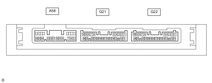
Disconnect the G22 certification ECU (smart key ECU assembly) connector.
-
Measure the resistance and voltage according to the value(s) in the table below.
Tech Tips
Measure the values on the wire harness side with the connector disconnected.
Terminal No. (Symbol) Wiring Color Terminal Description Condition Specified Condition G22-11 (E) - Body ground W-B - Body ground Ground Always Below 1 Ω G22-10 (+B) - Body ground GR - Body ground +B power supply Always 11 to 14 V -
Reconnect the G22 certification ECU (smart key ECU assembly) connector.
-
Check for pulses according to the value(s) in the table below.
Terminal No. (Symbol) Wiring Color Terminal Description Condition Specified Condition G22-6 (LIN) - Body ground R - Body ground LIN communication line Engine switch on (IG) Pulse generation
-
-
CHECK STEERING LOCK ECU (STEERING LOCK ACTUATOR OR UPPER BRACKET ASSEMBLY)

-
Disconnect the G26 steering lock ECU (steering lock actuator or upper bracket assembly) connector.
-
Measure the resistance and voltage according to the value(s) in the table below.
Tech Tips
Measure the values on the wire harness side with the connector disconnected.
Terminal No. (Symbol) Wiring Color Terminal Description Condition Specified Condition G26-1 (GND) - Body ground W-B Body ground Ground Always Below 1 Ω G26-7 (B) - Body ground B - Body ground Battery power supply Always 11 to 14 V -
Reconnect the G26 steering lock ECU (steering lock actuator or upper bracket assembly) connector.
-
Check for pulses according to the value(s) in the table below.
Terminal No. (Symbol) Wiring Color Terminal Description Condition Specified Condition G26-5 (LIN) - Body ground L - Body ground LIN communication line Engine switch on (IG) Pulse generation
-
-
CHECK ID CODE BOX (IMMOBILISER CODE ECU)

-
Disconnect the G15 ID code box (immobiliser code ECU) connector.
-
Measure the voltage and resistance according to the value(s) in the table below.
Tech Tips
Measure the values on the wire harness side with the connector disconnected.
Terminal No. (Symbol) Wiring Color Terminal Description Condition Specified Condition G15-5 (GND) - Body ground BR - Body ground Ground Always Below 1 Ω G15-1 (+B) - Body ground GR - Body ground +B power supply Always 11 to 14 V -
Reconnect the G15 ID code box (immobiliser code ECU) connector.
-
Check for pulses according to the value(s) in the table below.
Terminal No. (Symbol) Wiring Color Terminal Description Condition Specified Condition G15-2 (LIN1) - Body ground SB - Body ground LIN communication line Engine switch on (IG) Pulse generation
-